Building a Norwalk Islands Sharpie 18
Background
I've had the boat building urge since getting involved with sailing in college. My father had similar urges, only his dream involved a house. I lived in that house for 16 years without it ever being finished, so I figured that I should pursue a more realistically achievable goal.
So I began innocuously enough with the purchase of the NIS 18 building plans followed by the Jim Wharram designed Tiki 21. The house I rented had a large single-car garage, so I picked the Tiki 21, the maximum size I could build. Over the next 5 years, many things happened in my life that hampered the construction process. Marriage, moving, career change, and starting a family to name a few. The latter decision facilitated a move of my shop from a 30 ft. storage unit to a 20 ft. storage unit. This was a bit of a dilemma since the Tiki is 21 ft. long. I spent 230 hours on it so both hulls were mostly assembled. The size of it started to make me nervous. At 12 ft. wide with 3 beams, decking and netting, mast and rigging, it became a bit daunting to think about trailering and launching it myself. So, after many hours of introspective thought, I made the decision to cut the Tiki up and haul it to the dump. I realize that this action would stop the heart of any boater, but it was actually very instructive. I took the opportunity to demolish it in a way that would show me the strength of differently glued joints. In most cases, I was impressed. In any case, the Tiki became known to me as Failure #1 .
My next attempt at boat building madness was procuring the plans for a Bobcat, a Phil Bolger designed plywood Beetle Cat. I figured that it was small enough to handle easily by myself and construct in a reasonable amount of time. I even bought the cut-out templates from Peter Spectre/Compass Rose. Boy, that was really slick. Just plop the template down and draw. No measuring for hours. This had the hope of making the "40-hour" construction actually approach 40 hours. But, alas, after only cutting a few pieces, an impending divorce and subsequent move reduced my building to yet another trip to the dump. As such, the Bobcat signed into history as Failure #2.
As life can be somewhat circular at times, I returned to eyeballing the NIS 18. The attributes of being small with a nice cabin, simply rigged and simply designed were very attractive. I've always admired Bruce Kirby's work and knew that he would design something fun to sail. Besides, my garage on my new house is 20 ft. long, just long enough for the 18.25 ft. required to build it. The cabin will allow overnight (or more) trips or just getting out of the weather. The shoal draft is perfect for sailing around Chesapeake Bay. It's small enough to easily launch, rig and sail myself. So on Thanksgiving 1998, I started construction of what I hope will become Success #1. That will not be its name, by the way.
The Boat
The Norwalk Islands Sharpie is a line of boats from 18 ft. to 31 ft. designed as a shoal draft weekender/cruiser by Bruce Kirby. He used the traditions of the Sharpie and the advent of modern building materials to draw a boat easy to build for the inexperienced. The simple cat ketch rig with unstayed masts is prevalent on most of the designs except the 18, where a single cat rig is used. Despite the shoal draft and internal ballast, Kirby showed in stability tests that the NIS concept is surprisingly more resistant to capsize than originally thought. I've never sailed on an NIS boat so I can't attest to sailing ability or seakindliness, but I do take comfort that the ancestral sharpies were very seaworthy in nasty weather and were banned from racing events because they were too fast.
Here are the specifications of the NIS 18.
Like some of her bigger sisters, the 18's centerboard is slightly off-center to make the accomodations below a bit more spacious.
Before I started this project I wrote Kirby to find out if any changes have been made to the design in the 10 years since I bought the plans. He sent me blueprints detailing 2 rig changes made by client request. One was providing a salty-looking gaff rig which would decrease the length of spars needed. The other was a simple shortening of the mast by several feet so that the normally powerful rig wouldn't need to be reefed so soon. Since I live in an area of notoriously light winds and would rather be overpowered than underpowered I'm going to opt for the original 30 ft. mast.
One major consideration I have for any boat is safety. The typical bulkhead style of construction lends itself well to the creation of watertight compartments. When completed, my 18 will have 11 separate watertight compartments which can also be used for storage. The ballast will be in the form of lead ingots, and I plan to attach them in a way that will enable me to remove them in an emergency. These things may never matter, but I rest easier knowing that I have options.
Auxiliary power is something that I have wrestled with in the past. Although the outboard motor on my Cal 2-24 was very reliable despite my abuse, it was a pain in the neck. Dealing with the fuel, its fumes, moving the motor below to lock it up, mixing oil in just the right amount, having the tanks bang back and forth when I tacked, nevermind the racket it made when running...it was all just a great open sore on my sailing experience. The small size of the NIS 18 will allow me to forgo any type of petroleum propulsion. I plan to build oar locks in the cockpit coaming, and just use a pair of 8 or 9 ft. oars. I figure that the dory-like hull will lend itself easily to rowing, but I'll reserve judgement until I actually get to that stage. At any rate, it still won't hurt to have the option built into the boat. Like my Sunfish, the main engine will be the sail.
The plans for the NIS 18 give pretty good step-by-step instructions for the building process. They are not as good as Bolger/Payson instructions where everything is detailed. For the complete novice I would recommend getting a couple of Payson's Instant Boatbuilding books and reading them over before starting anything. The important thing is to think everything through first before picking up any tools. If I come to a head-scratching point, I put the tools down to prevent making grievous errors that I'll regret afterwards.
Construction - I
Overview
The construction technique for the NIS 18 is similar to other plywood designs. The shape of the hull is defined by the bulkheads. The Tiki 21 and Bobcat were a "stitch and glue" type of boats, where copper wire was used to hold the bulkheads to the hull sections. The joints were then glued in with epoxy and fiberglass tape. This technique is pretty simple and doesn't require a building frame like more traditional wooden boat building. The NIS 18 requires a building frame, so this experience will be a bit different for me. The frame holds the bulkheads while the hull pieces are glued on. Each joint is held together by a cleat -- a piece of trim glued to both surfaces.
Since the boat is 18 feet long, it requires a technique to attach several sheets of plywood together. Even some of the bulkheads are too big to fit within a 4' by 8' section. I've read a lot about scarfing and will use that method to construct the chine logs and rails. But scarfing plywood at the recommended 8:1 angle requires a special tool and procedure that I'm unwilling to undergo. Having used the butt-block method before, I am using it here. It is simple, strong, and very quick to accomplish.
Deviations
I have decided to make a number of slight deviations from the original construction plan. Usually it's because I think it will make my life a little easier.
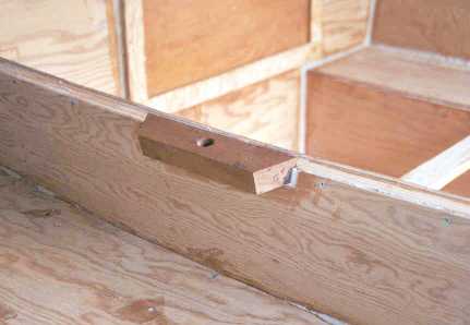
The first is to glue the cleats for the hull on the bulkheads before putting them on the strongback (the building frame). It's just easier to do and it actually helps eliminate some of the slight warping that is inevitable after each bulkhead is cut. I was careful to make sure that the cleats didn't interfere with the strongback components.
The construction plans call for 300 lbs. of lead as part of the keelson, being thin strips glued and bolted to the hull. This strikes me as being a true pain in the rearmost section, so I am opting to distribute that part of the ballast internally. How this is distributed will be covered later, most likely after I observe the boat in the water.
There a couple of minor design changes I will make. First, make the beam an extra 2 feet...no, just kidding. I am raising the floor of the port head to the same level as the bunk. I don't plan on putting a head onboard; I'd rather have the storage space/seat on that side.
Taking a clue from the longitudinal bulkhead under the cockpit, I'll be putting a similar bulkhead under the bunk. It will serve to strengthen the both the bunk and the hull underneath where it will probably be receiving the most punishment. It also serves to provide more watertight spaces for floatation. The extra weight overall will probably be around 20 lbs.
Progress Report - Start to Apr. 1999
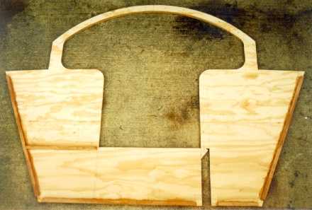
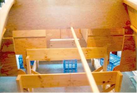
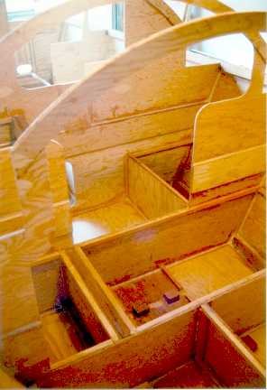
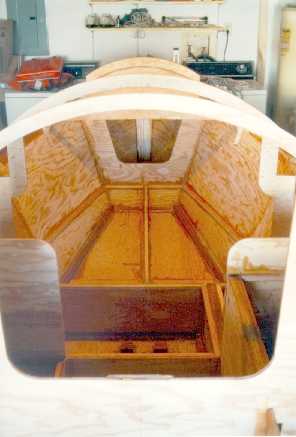
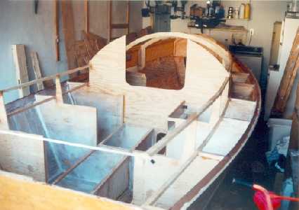
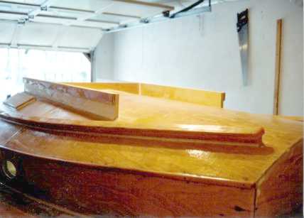
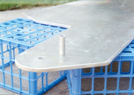
The first stage has been mainly focused on 2 major steps: building the bulkheads and the centerboard trunk. Including the transom there are 8 bulkheads, labeled A through G (the transom doesn't get a letter, it must have flunked high school athletics). Bulkhead B merely functions as the forward cabin end and doesn't extend much below the deck.
These images at right show the bulkheads in order from the bow (at top) to the transom. Bulkheads C, D, and E were too big to fit on a single sheet of plywood, so I had to form them from 2 sections. I chose to match the sections together at the reference waterline which is clear of any structural members.
A note here on waterlines. There are two: the displacement waterline, where the designer expects the boat to rest in the water when properly loaded, and a reference waterline. Kirby has drawn the reference waterline exactly 1 foot above the displacement one to aid in measuring all of the different components and also to lay out the boat correctly on the strongback. This line, along with the centerline, is drawn on each bulkhead on both sides, making further alignments easy.
The slot cut into bulkheads D and E betrays the location of the centerboard trunk. It is located 1 foot to starboard of the centerline. If it was on the centerline, it would not only severely hamper the area in the cabin, but it would also cut into the cockpit. I remember seeing a beautifully kept catboat many years ago at a wooden boat show in Port Townsend. It looked especially sleek with low freeboard and inconspicuous cabin. Unfortunately the large centerboard trunk come up almost to the cabin top! I am thin, but it would take someone even thinner to utilize what little space there was below. Kirby has done a good job here to remedy this problem without much detriment to performance. I don't expect the centerboard to show above the waterline unless the boat is pressed over 35° or more to port.
The funny notch in Bulkhead F is also centerboard related, allowing the block and tackle that raises the board to run back to Bulkhead G. Both F and G show the shape of the cockpit and coaming. The cockpit seat is level, but the floor slopes down to the transom.
Also quite evident from these bulkhead photos is the distinctive sharpie hull shape known for ease of construction.
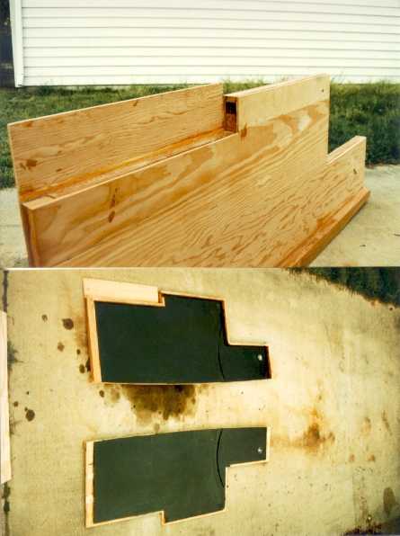
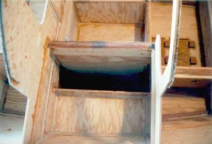
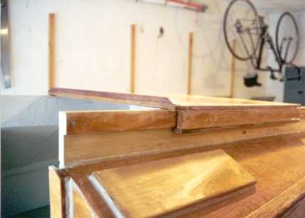
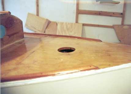
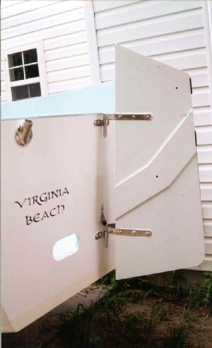
Here is a closeup of the transom, looking at the inboard side. The glued section is reinforcing for the gudgeons. The 2 holes are cockpit drains. Just visible are the lines drawn for where the cockpit will meet the transom.
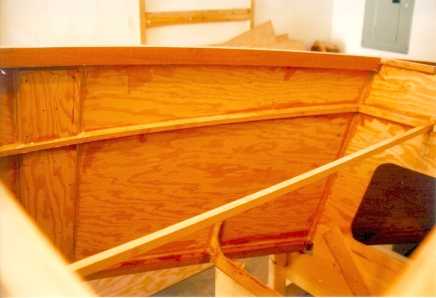
This shows both sides of Bulkhead E, the topmost being the forward side. Notice the butt blocks for joining the top half of the bulkhead to the bottom half. It is 6" wide so it overlaps both sides by 3". The vertical buttblock is for reinforcing. I plan to put a big U-bolt on the aft side to use for safety harnesses. I figured that having some extra wood there wouldn't hurt. The butt blocks at the cabintop curve is common to all of the cabin bearing bulkheads.
Looking at the aft side of the bulkhead shows the cleats glued for taking the hull sections. They do not go to the corners because those will be cut out for the chine logs and centerboard trunk bedlogs.
Again, the slot for the centerboard is clearly seen. The other larger hole is to provide access to an otherwise inaccessible space under the cockpit. All the other spaces will be accessible from hatches in the cockpit seats.
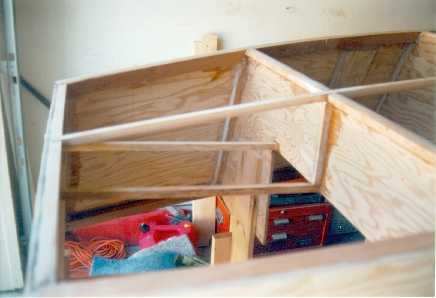
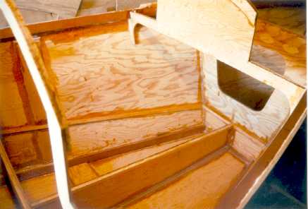
This is a picture of Bulkhead D looking at the aft side. This shows the space of the cabin interior. An additional cleat has been glued on the port side to indicate the position of the seat. This is the aforementioned floor that I decided to raise for additional storage space.
I have not cut out the trunk slot completely in this picture so the bulkhead would retain some stiffness. Once the slot is cut the bulkhead is pretty floppy. After it is glued to the trunk, though, the stiffness will return.
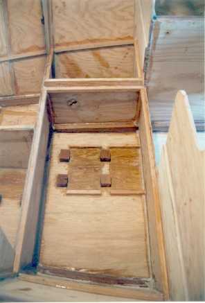
These 2 pictures show the centerboard trunk apart and together. The black interior is not paint, but epoxy mixed with graphite powder to give it some sense of lubrication. The interior width is 3/4" and the board will be 1/2" so it won't be that tight fitting.
The extra height on the port side sheet is a small change I made to the building procedure. Since the port side of the trunk coincides with the cockpit, I extended that section to the top of the cockpit seat to give it some continuity and strength.
The hole you see in the aft middle section is where the centerboard control line exits the trunk, and that is also where Bulkhead E is located.
The curve of the hull was measured on one side, and the other side was cut to match. The bedlog at the base of the trunk was not bent, but glued on oversized and then cut to match also.
I had to do all of the glueing of the trunk on my kitchen floor because it was too cold in my garage for the #2 Hardener to set.
The final part of this construction phase is to prepare everything for being assembled on the strongback. Once I glued together the centerboard trunk, I took the liberty of fitting the 4 bulkheads (C, D, E, F) on the trunk. Everything seemed to match up correctly. I didn't see any glaring errors, which is good. I made the cuts for the chine logs in the bulkheads and a few other minor items.
The next step is mostly a mental one. To say goodbye to all my garage space before assembling the strongback. I won't see that space again until I roll out a completed boat maybe a year down the road.
Construction - II
Progress Report - Apr. to Sept. 1999
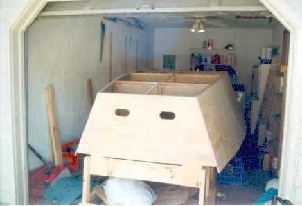
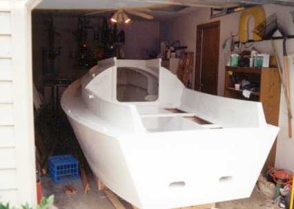
Well, a phenomenal amount of progress has been made, so it's high time to give another progress report. Currently I have spent around 130 hours on construction. Quite respectable since it took me 5 years to get to 230 hours on Failure #1. The most obvious change from the previous page is that the boat has gone from 2 dimensions to 3. Now at least I have something to show any visitors. Curiosity even got the better of my neighbors who eventually asked, "What is that?!?"
My comment last time about saying goodbye to the garage space has come to fruition as you can tell from this picture. The strongback was built first, which holds each bulkhead in position. I used a rented Dumpy level (like a transit on a tripod) to locate each bulkhead precisely. I couldn't use the garage floor as a guide because like most garages, it is not level. The most difficult bulkhead to position was the transom because it is at a slight angle. After a thousand measurements and adjustments, I finally had it as close as I could. Each bulkhead is held to the strongback with temporary screws. Now, the strongback is supposed to be strong, right? Yes, well, regardless of how strong it is, at this stage each bulkhead wobbles a bit. I didn't worry too much about it because I had a plan to help anchor each with some of the stringers that would eventually be installed anyway.
A note here about measurement tolerances. My goal at the beginning was to build the boat within 1/16 of an inch to the designer's plans. Hah! Further experience has shown me the folly of this idea. I'll be extremely glad if I'm within 1/4 inch or even a half inch in some places. But I'm not worried that I'll have a crooked boat. The critical parts, like bulkhead alignment, I know to be really close.
The next step was to insert the completed centerboard trunk. A moment of heartstoppage was followed by elation when the whole thing slipped into place. Everything matched up, except for a slight twist in the aft part of the trunk that I knew to be correctable. That's the joy and reward of building something like this. Seeing the parts built separately fit together as if divined to be. With that, the serious gluing and screwing began.
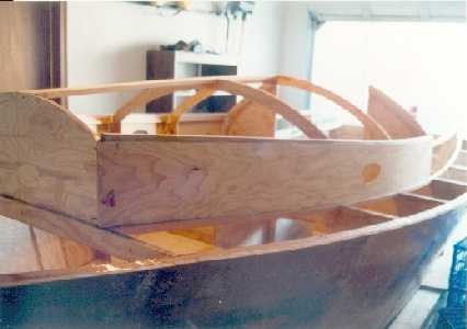
This picture gives a scan of the bottom and all of the integral parts. The centerboard trunk anchors 4 bulkheads together solidly. A cockpit stringer, shown in the lower center of the photo anchored the aft bulkheads together. Then it was time for the chine and sheer logs.
The chine and sheer logs are made of Honduras mahogany scarfed together to make a single 20 ft. long board. What I learned about this wood is...it doesn't like to bend. Not only was it supposed to bend around the bulkheads, it also needed to twist somewhat from stern to bow to follow the natural (?) curve of hull sections. I could only think of one solution to this dilemna. The Spanish Windlass. If you are unfamiliar with this concept, become familiar pronto. It is one of the most useful boatbuilding tools I know. Over the span of a couple weeks, I forced the logs into position and then let the area's humidity and heat take care of the rest. When I sprung them free to start the gluing process, they had already assumed most of the shape and didn't need quite the coaxing to get them into their final resting place.
This brought me to my most serious headscratching moment--what to do with the stem. The stem was already cut (oversized) and planed into shape, but it needed to be on an angle like the transom. The strongback didn't extend far enough for me to attach it, so what to do, what to do. I finally screwed a board to the stem that would stand on the floor, and the rest was glued and screwed in the proper position to the sheer and chine logs. Easier said than done, but it eventually did as it was told and was straight on center at the end. I did lots of checks first, because once the glue and screws are in, that's all folks! Very shortly after the logs were glued in place, I quickly worked on installing the hull sides because they would help keep the logs in place as well. I had this recurring nightmare of the glue failing and the logs flying off the hull like a giant spring. It didn't happen.
Putting together the topsides of the hull I once again departed from the building recommendations. Instead of piecing together the panels on the boat, I glued the panels together with butt blocks first and then placed it on the hull all at once. I admit that it's unwieldy to handle a 19 foot long piece of plywood, but I survived. I was familiar with this technique on Failure #1 so I stuck with it.
Now a note about plywood that I alluded to earlier when I was talking about a slight warp in the centerboard trunk. I used Marine Grade Fir plywood for this project. After dealing with a number of different types of ply over the years, I have come to the conclusion that it is impossible to make a 4 X 8 sheet that is perfectly straight and flat. Even if you bring it home flat, a few weeks storage in your garage will invariably turn it into a potato chip. Well, maybe I exaggerate. Fortunately, most surfaces on a boat are not straight, so I've made a habit of seeing how a sheet behaves first and then cutting it where it will follow the shape of the boat.
A note about measuring, cutting, and running out of things. It's always best to glue on a piece too big, then trim it later to size. Glue on too big, trim to size. Glue on too big, trim to size. Well, you get the idea. It's pretty important. One small mistake and it's another trip to the lumber yard to plunk down $200 to try again. Or worse. As for running out of material, make sure you have enough of something before starting a job where you can't stop. I was glueing one of the topside panels when horror of horrors I ran out of collodial silica filler before I got to the end. Since I can't glue this without some form of filler and I couldn't stop part way through, my panic found me using fine sawdust as a substitute. It has similar properties as silica so I wasn't too embarrassed in the end. But lesson learned.
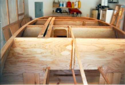
Here is a view of the inside of the boat looking aft from the forward end of the bunk. This gives a better picture of how the bulkheads are attached to the strongback. Although it's a bit disorienting, you will recognize the shape of the bulkheads from the previous page. The center stringer helped secure the forwardmost bulkhead (A) to bulkhead C so it wouldn't wobble while I was installing the chine logs. This stringer will also be part of a longitudinal bulkhead under the bunk that I mentioned on the previous page under construction deviations.
Another view of the space between bulkheads A and C (B is just visible at the bottom of the photo). On the left is one of the 2 butt blocks on each topsides to glue the 3 panels together. The stringer glued on later will hold the bunk. Clearly visible are the chine log on top (of photo), and the sheer log on the bottom. I botched the bracing on the strongback for bulkhead A, not thinking about how the topsides and sheer log would attach. So I had to redo the bracing without moving the positioning. Must have had a special brain aneurysm that day. But my mess to fix it is barely visible here so I'm okay!
This shows the aft section. The transom is on the left, bulkhead G on the right. A longitudinal bulkhead will be attached to the center stringers, dividing the part under the cockpit into 2 compartments. This part will be done after the boat is turned over and before the cockpit is assembled. More visible here is a white epoxy fillet along the connection of the topsides to the bulkhead. Plywood is extremely sensitive to water entering the end-grain so I've religiously sealed every joint. These fillets are perfect for that little bit of left-over epoxy that you don't want to go to waste. All the other surfaces will be coated with epoxy later to further prevent water penetration.
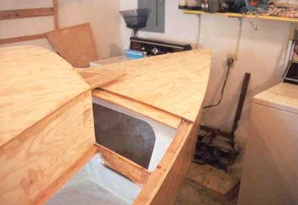
Here's a nice picture of the bow, neatly nestled between my washer and dryer. The brown bag in the corner with the 7 inches of sawdust on top is my golf clubs. The plans call for a 5-1/2 inch radius curve from the stem to the hull bottom. I cut the radius in a scrap piece of plywood to use as a template and then let the belt sander take its toll.
A brief comment here about the stem. I used the plans to figure the angles and shape the stem. It's a bit weird since it has to taper from a wider angle at the sheer to a much narrower angle at the bottom. The moment of truth came when I installed the logs. The top was perfect, but the bottom was not. In reality the angle of the logs was a bit more acute. Some sweating and epoxy filler saved the day, but my advise to future builders is to find what the angles are in reality before cutting the stem. The ol' saying "Your mileage may vary" applies here.
The plans show the 1/2 inch ply bottom extending over this knuckle and up the stem to deck level. Ever try to bend 1/2 inch ply over a 5-1/2 inch radius? Well, even 1/4 inch ply breaks. Taking a clue from Failure #1, I soaked 2 pieces of 1/4 inch ply in hot water and carefully bent them over the radius. The 3-layer ply indicated lots of stress but it didn't fail. After it dried out I glued and screwed them in place, using copious amounts of silica filler. Fir plywood is fairly soft, but when heavily coated with epoxy/silica and then fiberglassed it'll be impervious enough to do a bow proud. Not that I plan on testing it or anything. Sailing will be test enough, I suppose.
Here's a closer look at the port side of the transom. The top shows the chine log and topside plywood has been planed down to match the angle of the hull bottom (basically level with the floor). The other side shows how the ply has still been left oversized. It will remain too long until the deck is ready to be installed. The ply also extended beyond the transom by about 2 inches, but has been sanded down flush in this picture.
Finally, a picture of the sheer looking from the transom forward. If you step away from the monitor a few feet and squint your eyes just right, you can tell what the sheer and cabin/coaming looks like. Actually this might be better in describing the amount of space I have to negotiate when doing things inside and around the hull. My son doesn't have a problem getting around, but he's a bit smaller than I (his tow truck stands ready in the foreground).
More detail on the strongback construction is shown here as well.
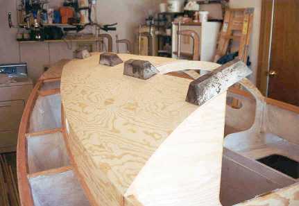
At press time the bottom sheet of 1/2 inch plywood has been cut to shape and glued together with butt-blocks. The lead pigs, made by a local castings place, now sit near the bow.
A word here about my evolution on ballast. I have devised a plan to secure the pigs by surrounding them with blocks of wood so they won't move and then lash them in place with lines attached to the blocks. The lashings would keep them from coming adrift during a knockdown or (heaven forbid) a capsize. The lashings will also allow removal during maintenance or a dire emergency. It will be easy to manage the ballast depending on loading, wind conditions, trim, and other circumstances. I won't shift anything once underway, but it allows some flexibility in how the boat can be set up. The designer requires a minimum of 600 lbs. of ballast with notice that the builder could increase it up to 800 lbs. So I purchased 700 lbs. as a reasonable start.
So at the moment I am gluing some 40 blocks to the bottom ply before I attached it to the hull. There are two reasons for this. First, I want to screw everything in place on the entire hull before coating it with fiberglass. That way I won't have to put a screw through the coating later, creating a possible source of moisture ingress. Second, gluing and screwing these blocks upside-down after the bottom is installed would be nigh impossible.
Then the next step will be attaching the bottom and fiberglassing the hull. That will entertain me for the next couple of months. Fiberglassing is something I never did with the other projects, so it will be a new experience. Rest assured that I'll be doing lots of reading up on it before I break out the cloth. After that I'll be doing the "turn-over" ceremony. Hoo-boy!
Construction - III
Progress Report - Oct. to Dec. 1999
Another very productive period. October saw a new personal record with a total of 37 hours of work for the month. Most of this was tied up in a short week (or long, depending on how you see it) of continuous fiberglassing. My parents often lamented during their house building that you became an expert of a task only when you didn't have to do it anymore. The same could be said of my experience with fiberglass. I didn't start off slow with test panels and different methods. I just jumped right in with the first layer on the bottom and went to it.
But I get ahead of myself. First came the installation of the bottom part of the hull. Not easy, seeing how I needed to maneuver a 17 ft. long sheet of 1/2 inch plywood. Since I didn't have an army of hands to help hold it up whilst I applied the epoxy goop, I cheated and used boards clamped to the bulkheads like stilts. Once I was ready, I lowered the stilts and started turning the holding screws like mad. Once done, I had over 200 screws in the bottom panel, about 125 to hold the ply to the cleats, and the rest for the previously installed ballast holders. Like the bone-head that I am, all of the screws in this boat are hand turned; I don't have a drill attachment. I'm sure that when I'm done I'll have forearms and wrists like Popeye.
So after some sanding to clean all of the corners, and installing several center stringers inside, it was time for the 'glassin'. After some amount of thought of how I am going to use the boat, I decided on putting a layer of 20 oz. triaxial on the bottom only, then covering the bottom and topsides with 10 oz. woven cloth. So after cutting everything to size, I was ready to roll. My initial plan was to proceed as follows:
- Coat bare plywood with epoxy. Let it become sticky.
- Roll on the fiberglass. Adjust as necessary so everything lays flat.
- Starting at one end, coat liberally with epoxy, using a squeegy to spread around the excess.
- Let it harden for 24 hours.
- Coat with more epoxy, filling the weave.
- Done, break out the brass band and sip champagne.
The 20 oz. stuff went pretty well, but then it was on a largely flat surface. This photo shows the progress. The white section is the cloth that hasn't been wetted out yet. Notice the centerboard trunk is gone. I glassed right over it, cutting it out later. I found that the cloth didn't like to lay flat when I got closer to the stern (I started the saturation process at the bow). After some amount of cussing encouragement, it stuck but was still not smooth. Another dream down the toilet. I figured that if I was careful, everything would be nice and smooth so I wouldn't have to endlessly fair the hull at painting time. Hah!
Okay, next thought. If I put filler in the epoxy when I fill the weave, maybe it will smooth out the lumps. After 5 feet of applying that philosophy, another dream followed down the toilet. It wound up being hard to smooth and was using an inordinate amount of epoxy. So even more fairing is now required. Aarrghh!
Then it was time for the topsides. This was a bit more challenging because the angle was nearly vertical at the bow, becoming less so toward the stern. Once I started to roll the cloth on the port side, it became apparent that my technique in Step 1 was tremendously flawed. The cloth wanted to stick, but not where I wanted it to, so there was an infernal amount of time spent adjusting and trying to move the cloth. Again starting at the bow, the coating process created bumps in the cloth starting about halfway back. A tremendous flaw in Step 3. But since everything was now stuck, so was I. The bottom layer of 10 oz. went quick with no problems, but then I didn't expect any. The starboard topside, though, was where I had a chance to redeem myself.
Indeed, I attacked the last part with an adjusted process:
- Coat bare plywood with epoxy. Let it become hard.
- Roll on the fiberglass. Adjust as necessary so everything lays flat, using tape if necessary .
- Starting in the middle, coat liberally with epoxy, using a squeegy to spread around the excess.
- Let it harden for 24 hours.
- Coat with more epoxy, filling the weave.
- Done, break out...um...okay, just listen to the stereo with a root beer.
Low and behold the starboard side is a work of art. Several days later I finished off the transom. The sections where the cloth bubbled up I cut out with a razor blade and filled in with epoxy and silica. That'll fix 'em!
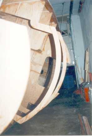
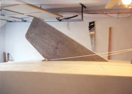
Time for the Turn Over?!? Nope, not just yet. I wanted to attach the skeg first. The skeg was a scarfed 17 ft. length of poplar with the outside edges routered smooth. (No, I haven't sprung for a router, I just used a woodworking friend's machine.) Soon after I glued and screwed it down, I planed the ends so there was a smooth transition from the skeg to the hull. I had some sections of 10 oz. fiberglass cloth left over from the bottom job, so I pieced together enough to glass the forward 2/3 of the skeg. That should take the most abuse during a grounding or beaching. The rest was coated liberally so everything was sealed up. Then it was officially time for the...
Turn Over
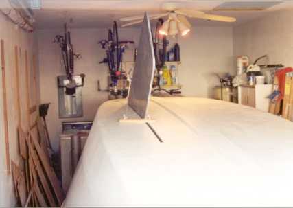
So on a foggy dark night, I began. The plan was simple. The next two photos show it clearly. An endless loop of rope was run under the bow and through blocks in the ceiling. I used a 3:1 purchase shown in the middle of each picture to adjust the tension. Another loop ran under the stern.
After tightening them as much as I could, I started the exciting process of detaching the strongback from each bulkhead.
Slowly each support was dismantled and eventually, the boat was fully supported by the rope slings. I cleared out the rest of the strongback, swept up, and this picture shows the result.
Now for the turning. I simply grabbed the starboard rail and started pulling up. The boat turned very smoothly until the port gunwale came to rest on the garage floor. Hmm. Obviously I had to raise the boat some so the whole boat would clear the floor. Time to take some pictures.
Here we see both sides of the boat. Well shown is the newly installed skeg and the cutout for the centerboard.
So I huffed and puffed on the bow sling to raise the bow up 2 ft. Once clear of the floor, the hull really wanted to turn upright. It took some effort to hold it back so the rest of the journey would not be a violent one. Turning continued inch by inch and then it was...
Upright!
Letting it down on the precut blocks was a breeze.
I would have celebrated, but at that point I was too tired. I went to bed instead. But I was extremely satisfied with how everything worked out. I was able to turn over an 18 ft. by 6.5 ft object weighing 400-450 lbs. by myself without even breaking a sweat. Pardon me while I break my arm patting myself on the back.
This whole event occured almost exactly 1 year after I started cutting the first piece of wood. Time spent so far is about 200 hours.
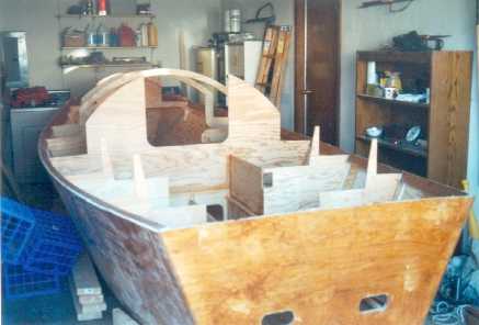
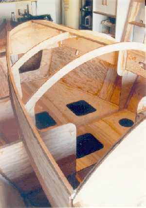
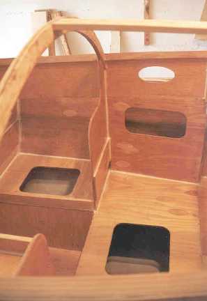
The new perspective inspired more work. Now at least I can see what I'm doing. First up was installing the longitudinal bulkhead under the cockpit, shown here.
Decisions made a long time ago show up here. Remember the extended panel on the centerboard trunk on Page 1? It's here at the left corner as part of the cockpit wall. I love it when a plan comes together.
These pictures show the basic interior between bulkheads E, D, and C. Visible here are the blocks that I glued in to stabilize the lead ingot ballast. Eyestraps will be screwed to the blocks so that the ingots can be lashed in place with rope. I fiberglassed the ingot locations without filling the weave so it would provide a non-skid surface. Even if they do move around a little, the chafe will be on the glass, not the hull ply itself.
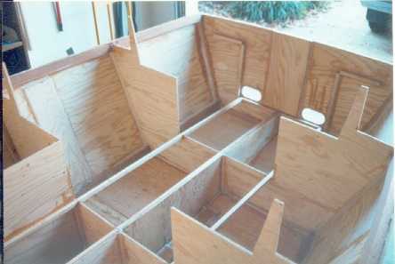
 Here's some more starboard side detail between bulkheads E and D. What you see here
is the first piece of furniture that I installed while
the boat was still upside down. It's a non-structural
shelf with a fiddle. I thought it would be a handy
storage spot under the "galley", and will be
accessible through a watertight inspection hatch.
The plans didn't call for the shelf, but I thought that
without it the space would be difficult to use after the
"galley" top was installed.
Here's some more starboard side detail between bulkheads E and D. What you see here
is the first piece of furniture that I installed while
the boat was still upside down. It's a non-structural
shelf with a fiddle. I thought it would be a handy
storage spot under the "galley", and will be
accessible through a watertight inspection hatch.
The plans didn't call for the shelf, but I thought that
without it the space would be difficult to use after the
"galley" top was installed.
So I huffed and puffed on the bow sling to raise the bow up 2 ft. Once clear of the floor, the hull really wanted to turn upright. It took some effort to hold it back so the rest of the journey would not be a violent one. Turning continued inch by inch and then it was...
Upright!
Letting it down on the precut blocks was a breeze.
I would have celebrated, but at that point I was too tired. I went to bed instead. But I was extremely satisfied with how everything worked out. I was able to turn over an 18 ft. by 6.5 ft object weighing 400-450 lbs. by myself without even breaking a sweat. Pardon me while I break my arm patting myself on the back.
This whole event occured almost exactly 1 year after I started cutting the first piece of wood. Time spent so far is about 200 hours.
This picture is very similar to the 4th picture on Page 2, only the boat is right-side-up. This also shows the longitudinal bulkhead that I mentioned in my Deviations section. It will provide additional support for the bunk, as well as strength for the bottom hull panel.
My plan for the next few months is fairly chaotic. The builder's instructions call for epoxy coating, installing the bunks and cabin carlins, but I have lots of little details to attend to which I'll work on in no particular order. I've started cutting the bunks to see what I've left for material.
One comment about material. Different designers have different philosophies when it comes to helping the neophyte. Wharram not only gives a material list, but shows you exactly how to lay out each piece so you minimize waste*. Kirby just gives an approximation of what each piece will consume (Blkhd B = 0.25 sheet, Blkhd C = 0.3 sheet, etc.) then adds them all up. So you blithely walk into the lumber supplier and say "Gimme 13.5 sheets of 3/8 ply!" like the plans indicate. Down the road, the error of this method becomes clear when you try to cut odd shaped pieces out of even odder shaped scrap and it doesn't work. This is why I've just bought material as I've gone along, but you won't get any volume discounts doing this. The amount of waste really depends on where the material goes, but figure on at least 15% - 20% waste to be safe.
Here's my H. Hornblower picture where I imagine myself sitting in the cockpit and sailing into the sunset between my washer and dryer. There's something not quite right about that dream, but I haven't figured it out yet. Maybe it's that the only water here is inside the heater off the starboard bow.
Anyway, back to the details. Lots of cleats need to be glued to take the deck and cabin sides, nearly 70 eyestraps for lashing down the ballast, and then epoxy coat the interior parts below the bunks and cockpit. Then I'll be ready to glue down the bunk parts.
There are a few things looming heavily over the horizon that'll I'll need to start some research on. The first is the mast tube hardware. I might throw in the centerboard, too, since both are made of aluminum. Next will be the mast, since it will probably take a good amount of time to have it built.
At press time I've already cut and fitted all of the "furniture". I'll glue them in place later. I've started coating the spaces under the bunk with epoxy and white pigment to seal the wood and give it a slightly finished look. I've also installed the cabin top carlin and am part-way through installing the cabin side carlins. It's interesting how things are taking shape.
* What was a good idea that didn't pan out in practice. Wharram showed how all pieces requiring 5/8" ply could fit on one 4x8 sheet in his Tiki 21 plans. Regardless of how I measured things they wouldn't fit. So I had to purchase another sheet (for $75!!!) and used a very small part of it. Was I mad? You betcha! But not as mad as when I discovered that Wharram's dimensions for Bulkhead A were too short. Of course this discovery occurred when I was installing it. It made me believe that Wharram may be an inspired boat designer, but he's no engineer.
Construction - IV
Progress Report - Jan. to Mar. 2000
My Y2K testing began on January 1 by waking up and turning on the light. It came on so that was good. The next test was to open my garage door and see if the boat project was still there. It was. Unfortunately no Y2K elves (opposite of bugs) finished the boat for me, so there was no choice but to dig in.
I mentioned in my last page that I was doing things in a chaotic fashion and this continued to hold true. A quick look at the building instructions revealed that I was working on 5 line items at once. Essentially, the order I've been proceeding has depended on how I perceive things to be several steps in advance. There is no good or bad way of going here, just personal preference, most likely.
From the last sequence of pictures, the most obvious is the slow development of the cabin house. The center stringer is in place, as are the carlins that form the cabinsides and coaming rail. The curved bulkhead tops that used to be slightly wobbly are now firmly locked into place. That gives me comfort because I need them all the time to help me climb in and out of the boat.
My plan was to use up my supply of 1/4" ply to put the cabinsides together. Since we're getting down to the short strokes I don't want to buy more material than I need. The side stringer is still oversized (or stands proud, as traditionalists say); it will need to be planed down to match the cabintop. At this stage, there are precious few measurements listed in the building instructions. Mainly because you don't need them. Most measurements are taken off the boat and transfered to the material. It takes a bit longer, but at least everything fits in the end.
Obviously my camera angles haven't improved much. It's a bit limiting when the boat fills up the whole working space (have I mentioned that before?). So you'll have to bear with me until I can get the whole contraption into a different setting.
This picture shows how the interior is progressing. The bunk platform has been glued and screwed down. The things left to do in this picture are glueing the port "head", the starboard "galley", and the hand lockers on each side (located below the porthole in the cabin side).
Everything has been glued together with an eye that it serves a structural function. So each seam is glued, screwed down every 7 - 8 inches, and then given an epoxy/silica fillet. The designer's notes mention the need to distribute torsional stresses by installing the furniture and deck so they form one homogeneous unit with the hull. I can say that the hull itself is pretty solid right now, based on how things went in the Turn Over. Now with the bunks, and eventually the deck, it should go from pretty solid to rock solid.
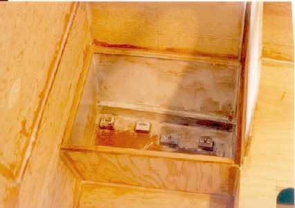
Here's a picture of the "head" on the port side. You can see the installed eyestraps that will help hold the lead ingots in place. Also slightly visible here is the epoxy coating mixed with white pigment. It's not pretty, but I'm looking for sealing properties here, not beauty. The white pigment was intended to make it look slightly finished, but as you can see, my formula isn't quite right (More pigment, Igor! More pigment!). By the time I finished the last coating near the stern, I had the shade to just about what I wanted.
This picture that shows the cockpit coaming carlins. A rope stretches across the ends because they aren't supported until the plywood portion is glued in. Speaking of plywood, the outside coaming and the cabin side is theoretically all one piece. I stopped at Blkhd E for now because it was a good place to divide the fore and aft sections. Plus it's easier to deal with smaller pieces of wood than larger (remember the topside hull panels...Uck).
For the outside coaming ply, I measured and cut the starboard side plywood first, then used it as a template for the port side. Hopefully this would make each side exactly the same curve (see boat profile on the Boat Page). For those places where the coaming carlin didn't match the curve cut in the ply, I forced it in place during the glueing/screwing, then sanded it smooth later.
This picture also shows another development in space reduction; my 3 bicycles now hang from the ceiling near the port bow. My son's bicycle handlebars are just visible in the lower right corner. Huh? Oh, right...I've mentioned the space problem before.
At this point several things have my full attention. The first is the rig. The designer recommends a fiberglass mast, since it would bend correctly and carry a lower center of gravity than an aluminum one. The recommended builder of these spars no longer exists, probably due to the owner's death in a plane accident. Other NIS builders have opted for spun aluminum, carbon fiber, or a combination of wood, fiberglass, and carbon fiber. Prices and techniques vary all over the map, so I'm still reserving judgement until I have as much information as I can.
The second attention draw is paint. What type, what system, what color? So I'm glued to brochures and other advice sources. Several builders have recommended painting the interior before the deck is on since it will be harder to reach those infernal nooks and crannies. So I'll be following that plan shortly.
Third item is the cockpit layout. Since the inside furniture phase is nearly complete, it's the only major section left. I want to install a traveller, since as a racer I enjoy the added control benefit. I also want it to be close enough to the hatch so I can reach it and the mainsheet from inside the hatchway (you know, so I can dump the main if caught in an unexpected gust). This and structural considerations pretty much dictate that it needs to span across the cockpit at Blkhd F. I'm sure that underway this will become known as the "shin-banger" or less politely formed descriptions. It also defines the mainsheet system as being "mid-boom" rather than "end-boom" arrangement. In addition to this complication, there will be 6 hatches in the cockpit seats to access the space below them. Although quite voluminous, the small hatch size may limit the use of the space. Maybe it won't be as bad as it looks now.
The 300 hour mark
So it has come to 300 hours of labor. The hours leading up to this milestone were spent mostly on the cockpit. As with most boats, this area is fairly complex and has required quite a bit of measuring, cutting, fitting, glueing, coating, and then repeating it all over again.
Another milestone done during this period was planing down the sheer log and top cabin side rails to their exact dimensions. Now for the first time the graceful shearline is evident and also ready to receive the deck. And with that, I've started cutting and glueing the forward deck pieces.
The bow forward of bulkhead A is the most structurally critical part of the whole boat. This is where the mast tries everything it can to tear itself free. As a result, the designer has indicated reinforcement at the hull bottom and the deck. The amount of doubling (laminating 2 pieces of ply together) at the deck was shown to cover the mast step area, but not all the way to the bow. I know I'm going to install a fairly hefty cleat forward of the mast, so I decided to double the entire area forward of bulkhead A. The next statement about using a continuous sheet of ply from the bow back to the cabin and beyond is logical but not practical. The difficulty is that the deck flares out beyond 4 ft shortly aft of bulkhead A. So obviously a butt block joint was needed, but where? After some engineering-inspired thought, I've decided to place a butt seam athwartships just aft of bulkhead A. The end result will be a foredeck that is almost entirely laminated to 3/4 inch thick, plus fiberglassed on the top.
I'm a stickler for wasted movement. I'll do anything to prevent having to make the same cut twice. But for the deck around the cabin and cockpit I'm putting aside this idiosyncrasy. Over this area the sheeting has to follow 2 curves: the hull curve at the gunnel, and the cabin/coaming sides. The outer curve at the gunwale is easy--just cut the sheets oversized like I've done many times before and pare them down after glueing. But the inside curve of the cabin and coaming affords no such luxury. So taking a step straight from "Dynamite" Payson's book, I clamped a scrap piece of ply next to the cabin and drew the curve using the block-with-a-pen-hole trick. Then by cutting the curve in the scrap, it'll serve as a template for the real piece. Fortunately I had the right sized scrap to do this. My lumber supply pile has disintegrated into a jumble of increasingly unusable junk.
Another milestone is deciding on going with the Interlux paint system. It's not really an endorsement of the company, just a decision based more on color choices and the amount of BTDT (Been There, Done That) information I was able to find. The most important thing, I think, is to stick with one product line. Mixing and matching different products from different companies could lead to tripping at the finish line if you don't know what you're doing. And I don't know what I'm doing.
Here are my interior paint plans:
- Coat interior with a thin layer of epoxy. Just enough to seal the wood
- Wash with water to remove any traces of amine blush
- Sand with 100 grit paper
- Vacuum, clean with Interlux Fiberglass Solvent
- Apply a coat of Interlux 404/414 Epoxy Barrier-Kote
- Sand with 100 grit, repeat 5 and 6 if necessary
- Apply coat(s) of Interlux Premium Enamel
I'll give an update on this system later.
Construction - V
Progress Report - Apr. to June 2000
Recently I was able to get my hands on a demonstration copy of Vacanti's Prolines 98. Heck, you can even get it yourself at their website. The demo version does not allow you to save your work, but I was able to enter the lines of my boat in about an hour. Once entered, the program gives a 3-D perspective of the hull (you can do the deck also if you have the full version) that you can turn and play with like a toy model. That's nice, but the real meat for me was the hydrostatic calculations. I put in the ballast (weight and location of each grouping of ingots), and then watched the program churn through the convolutions of slowly tipping the hull over. Now, lots of questions came up in my mind, like how does the program determine the CG of the hull without the ballast? But let's not allow the nitpicking facts get in the way of a good story. Based on this data, the program concluded that my vessel would reach its point of no return (capsize) at around 130 degrees. Whoa! That's better than many ocean-going yachts. Okay, back to reality. A more useful benefit from this exercise was showing how the hull tips in the water given a displacement of 1600 lbs. Specifically, the rail (or gunwale) touches the water at around 40 degrees of heel. That's pretty far over, by gum. After a few more experiments the program locked up, probably due to some internal demo clock so you couldn't design the next Carnival Princess.
All of this was an interesting sideline. I plan to conduct my own real life stability tests as part of the sea trials, but having this in hand will provide an intellectual comparison.
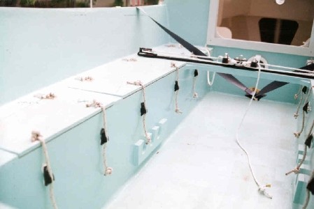
We'll start off here by showing a picture of the interior again, this time with the lockers in place (the piece below the elliptical porthole) along with the head and galley tops glued in. All surfaces have been coated with epoxy in preparation for a primer coat. Contrary to most everything else, the bottom of the lockers are not held in place by a cleat. I had to anchor them in place with a couple of nails while I applied a fillet on one side. After that solidified I pulled the nails and put another fillet on the other side.
Also visible here are fiddles installed on both the head and galley (shown in the lower left corner of the pic). Hopefully these will help keep things from flying around in a seaway. Later I will install several padeyes around the head hatch so I can tie things down, like a stove or porta-potti.
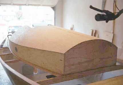
Time for the cabin top. Here's the first sight of my lead ingots, put to good use to hold down the 1/4-in. plywood until I can get all the screwholes drilled. Despite the amount of curvature and having a bit of compound curve near the forward end, the ply never complained. Warning - this stuff is 3 ply; the grain of 2 veneers run in the same direction. That means it will bend easier along one axis than the other. In this picture the grain of the 2 veneers is fore and aft.
One thing to be careful of here is making sure that all surfaces of the ply are snug up against all supports when you pre-drill the screw-holes. Also, start at one end and progress to the other. Otherwise you run the risk of the screw-holes not lining up properly.
And here are both sides completed, trimmed and sanded clean. The second half was more challenging because I couldn't use C-clamps on the center stringer. Instead I had to use 4 or 5 screws. Not a big problem, just a bit more awkward.
Now I had a choice. I could either glass the cabintop and then install the hatchrails, or the other way around. I decided to put on the hatchrails first, because I prefer to have wood to wood glue joints wherever possible. Whether this really makes any difference, I don't know. The only other thing left on the cabintop will be the handrails, and I'll put those on after I glass.
After this stage, I had to put a doubler in the inside aft 12 in. of the cabintop. This is designed to provide reinforcement for the cleats that will hold the running rigging. So the question was, how do I glue a piece of ply on an inside curve without punching holes in for screws and nails? I came up with some "stilts" that I could rest against the furniture inside and force the ply into position. Well, I guess it's hard to describe without seeing it, but it was a pretty simple setup.
Through the miracle of time elapse photography, here we have a sequence of how the cockpit went together.

Any questions? The leftmost is the cockpit at the time of the previous page. The middle has the outer cockpit railing, cockpit well sides, and traveller beam installed. The cockpit seat is also done, although that's harder to see. The rightmost has the cockpit coaming complete except for the rail cap, all cockpit hatches in place but not attached, and the cockpit floor is done. Notice the hatchboards as well. There were no surprises here, just a lot of little piece work. The only tricky part was fitting and glueing the cockpit floor, which is one continuous piece. Several steps were required to get the floor ply around the permanently installed traveller beam.
Here's a closer look at the cockpit seats. Each hatch has a frame around it to help seal it from water ingress. Although the aftmost hatch looks restrictive, it's still big enough to be able to reach most of the compartment below it. Remember that I have no limberholes in the bulkheads, so water will have to be sponged out from each section. The other hatch openings are big enough to reach everything easily. That comes as a relief, since I was concerned about having to become a monkey to retrieve an errant item underway.
The coaming carlin is still overlong after glueing the outside ply in place. I trimmed it down before glueing the inside coaming section.
Looking on the other side of the coaming, here's a closeup of the oar socket. There is still a 5/8-in thick rail cap to be glued on the top of the coaming, which is why the block sticks up a little bit. My intention here is to reinforce the oarlock location and spread the load over a wider area. Whether this is enough will become apparent when I actually use them. If I rip them off, well, I built the boat, so I think I can handle fabricating another solution.
It's hard to tell here, but the oarlock is installed at a slight down angle. I drew a diagram of the boat and a set of 9.5 ft. oars to see what it would look like. Due to the freeboard, it's a pretty good angle. So I set the socket around 8 degrees so it would prevent the oars from binding on the oarlocks.
So let's talks decks since we can see some deck next to the coaming. This picture shows the foredeck after it was glued in place. A butt-block is glued to the underside to take the next deck section. You can see primer on the interior. The next deck pieces I primed and painted the undersides since it would be more difficult to do it when they are installed. But there is a hazard with this plan. After they are glued in place, there is more filleting done inside. Those fillets, and other missed spots, have to be primed and painted also. In the process, epoxy, primer, and paint drips onto the parts already painted. So I have to go back and repeat the whole process again. So after doing the starboard side like that, I'm glueing on the port deck with just an epoxy coating. I'll take care of all the remaining priming and painting in one shot.
Speaking of painting, I've pretty much stuck to my proposed plan on the previous page. According to the Interlux literature I only needed one coat of primer (yes!). After 2 coats of the enamel, I think I'll probably need another coat in certain places to make everything look, well, truly snazzy.
Before I leave the foredeck, I've received the mast tube and associated metal pieces from a local machine shop. I needed the tube to accurately cut the hole in the deck and the brace near the mast step. Once cut, I was able to fit everything in place with satisfaction. I won't permanently install this part until after the deck is fiberglassed, primed and painted.
And finally, this picture shows 2 things completed--the hatchrails and the whole starboard deck. I'll say right up front that the fact that the hatchrails are perfectly parallel is a complete fluke. Measuring with accuracy on a slowly adjusting curved surface was hard work. I just did my best and crossed my fingers.
And the deck? Easy as pie. I used those cut templates that I described before and they helped tremendously. On the underside I have glued reinforcement blocks for cleats (the horn variety) and U-bolts. The U-bolts will be used to tie down a boom tent (an upgrade that I'll eventually get but I'm planning for it now) or an occasional fender. I also glued a couple of blocks for potential stanchions for lifelines. I don't plan to put lifelines on this boat, but if I'm forced to (at gunpoint), I'll have the extra strength there.
I can't describe the feeling of satisfaction after putting on the deck and standing back to admire it. It seems like getting it fully enclosed is the first step to getting its personality. No longer is it a random pile of boards cut at strange angles, or a skeleton with no comfortable way of getting around. It now has a skin to show the true purpose of its design.
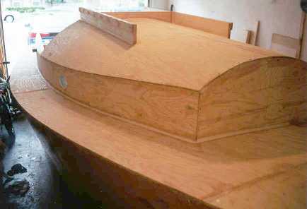
Another thing has happened that is purely an illusion. Before, it looked ungainly, huge, any moment about to swallow my garage. Now it looks a lot smaller, a lot more manageable, and the garage doesn't look so threatened. I'm sure that when I move the boat outside, it will look vastly smaller, at the launch ramp a small toy, on the ocean a minute plankton. But it will be my plankton that I had fun creating.
At press time I'm about to finish the rest of the deck, then I'll finish the priming and painting of the inside. After that I'll have no choice but to fiberglass the deck, the cabintop, and the cockpit. Oh, Boy!
Construction - VI
Progress Report - July to Dec. 2000
Believe it or not I feel like I'm getting to a point of termination. Whenever I leave a store I think, "That's the last (of that) I need to get." I don't need any more wood. I don't need any more epoxy. There's still a lot left to do, however, so I have learned to contain my enthusiasm.
The first part of this report period was spent putting the fiberglass on the deck, cabin house, and cockpit. Although somewhat more time consuming than the glassing the hull, everything went according to plan. Next was glueing on the finishing trim pieces and completing the sliding hatch cover.
This picture shows how everything looks on the cabintop. The handrails were made in 2 pieces because it conforms to a pretty good bend. The pad between the handrail and the hatchframe near the aft end is for a small winch and 2 cleats. I didn't put one on the other side.
This shows a bit more detail of the hatch. The plans suggest installing stainless steel pieces on the hatch to help it slide along the rail. I've decided not to do this for now; I'll wait to see how much it wears. I do know that shiny metal sitting under the summer sun becomes really hot, so I'm trying to avoid that situation. Epoxy doesn't like extreme heat. I designed the hatch so it can be slid forward off the rails at any time.
Turn Over II - The Sequel
I got a number of comments over the last year questioning why I had decided to turn the hull before I had completely finished the bottom and topsides. My answer was that I wanted to do the sanding and painting all at once, and since the turn over process was fairly easy I could do it several times. Not much wisdom involved here. But as I proceeded with attaching the deck, I found that my decision did indeed contain great wisdom. As I worked around the gunwale with the deck, fiberglass, and finally, the trim, little rivulettes of epoxy would run down the topsides. Had it been painted I would have had quite a bit of resanding and repainting to do (not to mention another problem detailed below).
I used the same technique as before, with some slight modifications. I reinforced the blocks in the ceiling, and used the mainsheet and boom vang blocks for more purchase to raise the boat. As expected, the line around the stern was tight enough to play a tune. Last time I didn't sweat; this time I did. The boat now weighs an estimated 850 to 900 lbs. and was no easy task to turn it by myself. Memo to me: Get help for the final turn-over.
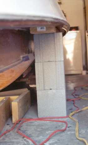
I got a question of how I supported the boat after I turned it over. It was pretty simple--shown in this picture. Four sets of these concrete blocks held up the boat and wood boards were placed on the top to protect the deck from the rough surface of the blocks.
After it sat on the blocks for a bit, I checked to see if there was any deformation of the deck around the blocks indicating too much stress. There was none. This boat is pretty strong so far.
Now having the hull upside down, I started in working on sanding and cleaning up what I call "pimples". These are small spots where the fiberglass has not adhered to the layer underneath so it shows up as a small discolored blister. As mentioned before I cut them out and filled the remaining space with epoxy filler. In this process I accidentally discovered some sticky goo in one part of the bottom. It didn't make any sense, so I investigated further. Poking my razor blade around I soon discovered that the goo was actually epoxy that had never hardened, and I could easily peel up whole sections of hardened epoxy from the never-hardened epoxy underneath. My reaction was a classic filmmaking moment:
Movie Director: "...and, Action!"
Me: "AAAAAAAAAAAAAAAARRRRRRRRRRRRGGHHH!"
Movie Director: "Cut!"
I kept rooting around and peeling up the top layer, some with 10 oz. fiberglass in the goo, until I got to where the epoxy had bonded correctly all the way through. It came to about 1/2 a square foot in area, but it really made me nervous. Were there other such areas? I checked carefully but everything was sound. So I filled the uneven holes with my usual patch of epoxy and collodial silica. I remember that during the bottom fiberglass job I was mixing up large batches of epoxy. Somewhere during the 10 oz. layer I didn't mix it thoroughly enough and this patch never solidified, although the succeeding layers did. I don't think anything bad would have happened had I never caught it since it was still sealed on all sides and water couldn't penetrate the wood. But it still goes to show that there can be goof-ups here and there. Memo to me: Fire the Quality Assurance Engineer.
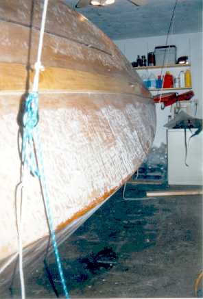
Then it was a-painting I do go! Two coats of the barrier epoxy were applied to the hull, then I taped 2 inches above the waterline and applied 3 coats of one-part polyurethane up to the rail. I followed the directions to the letter and everything went much easier than I would have thought. I don't plan to paint the bottom--instead leaving it as white barrier epoxy. The boat will not be in the water long enough to worry about growth.
The Centerboard
So I got this big chunk of aluminum plate cut by a machine shop to the right shape. But the leading edge is perfectly square. Not exactly hydrodynamic. So on the advice of my neighbor I used my belt sander with 50 grit paper and turned the leading edge into something closer to parabolic. Worked out pretty well and went quicker than I expected. The designer recommends tapering the trailing edge, but since the plate is only 1/2" thick to begin with, I'm not going to worry about it. The machine shop was supposed to drill the holes for the pin and the pennant, but they blew me off. That turned out to be a blessing since it gave me some flexibility of size and location. I hadn't decided until late in the game how the pin would be put together, and it turned out that the pennant attachment had to be moved.
This exercise also gave me my first experience with 3M's 4200 Fast Cure goop. I've chosen 4200 because 5200 is too permanent; I want to be able to undo it at a future date. All deck hardware and attachments will be sealed with 4200, and the centerboard pennant block and pin was an excellent starting point. I learned that the moniker "Fast Cure" means that it starts curing immediately after you purchase it at the chandlery. After buying the larger tube and having it solidify on me after the first application, I bought the smaller tube that has a screw cap so you can seal it back up. Much better.
After some thought on the subject, my plan for the centerboard pin was to eliminate any electrolysis caused by connecting dissimiliar metals in salt water. So I seized upon the idea of using an aluminum bushing between the centerboard and the stainless steel bolt that would hold the whole thing in place. A piece of aluminum conduit did the trick.
Here is the centerboard in its entirety followed by a closeup view of the bushing and centerpin hole. Notice also how the leading edge looks after having been rounded off.
Now came the really tricky part. After enlisting the help of my bride to install the pennant block inside the case, I was ready to put the board in. Well, let me put it this way: I was ready but the case was not. After struggling to get the board over the slot, it wouldn't go. "Doctor," I thought, "I'm feeling a severe pain in my chest." The board is 1/2" thick; the case is 3/4" wide. But my exuberance in sealing the end grain of the bottom sheet of ply made the slot much narrower. Less than 1/2". Out came my dremel tool and a-sanding I did go. Any exposed wood I had to re-seal with epoxy, so a week later I was ready to try again. This time it went in, but it soon started to bind with sounds of mangling wood. "Doctor," I thought, "Everything's fading to black!" The pennant cable shackle was not following the planned groove in the trunk (see Constr. I, barely visible in the last picture), so I had to move the attachment. Of course, more wood to re-seal. A week later a friend helped me maneuver the whole thing in place and install the pin/bushing. Then, the moment of reckoning was at hand. Slowly I let the whole thing slide down, and it did so with no complaints until it was all the way in! Well, almost, that is. It still sticks out about 3" on the aft end, probably because it is bumping into something like the pennant block guards I made. I don't mind at this point. "Doctor, I'm alive!"
Now a side view of the centerboard in place. The block and rope is to prevent the board from allowing gravity to take its course. The board is not extended fully here as it would bump into the garage door, but you get a good idea of the intended purpose.
Another picture before the board was sent home into the trunk. Here you can see the subtle change between the barrier epoxy and the polyurethane at the waterline. It's not much more than a change of gloss, which is exactly what I wanted. There will be no bootstripe.
But nagging questions remain. What if the board becomes jammed in the case? I have no mechanism in place to fix this problem. The hole at Blkhd E where the pennant wire comes out is inappropriate for any other use. I can see myself raising the board to go downwind in a race, reaching the leeward mark to go back upwind and not being able to get the board down. That would be, to put it mildly, a disaster. My thought now is to drill a hole in the top of the case just a few inches aft of Bkhd E. Then I could ram a rod down the hole to help things along. The hole could be plugged when not in use.
Turn Over III - The Final Episode
By now, a piece of cake. I did get a friend to help so I didn't have to sweat. Instead of setting the boat down on the floor like last time, I built a cradle out of scrap lumber to hold the hull. I'm hoping that this cradle will allow me to slide the boat out of the garage when the time comes.
Here's a gander at the foredeck, complete with the quarter-round trim that graces the rail. Again, since it is made of mahogany, it was tough to bend into shape. I screwed it in place, then after the epoxy dried I backed out the screws and filled the holes with more epoxy.
You can also see the half-round trim on the sides of the gunwale.
Oh-my-gosh! The whole deck is now primed white, ready for my color scheme. The change is quite dramatic, I must say.
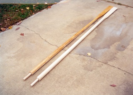
Lastly, I submit a picture of the oars. The one on the right is not coated with epoxy yet, the left one is. They are built to a stretched pattern provided by Jim Michalak . Made of 3 glued sections of ash, 9.5 ft. long, they were cut, planed, and sanded to this point. They'll be painted as well.
So it's back to sanding, sanding, a little painting, and sanding again. Most of it is now temperature dependent, and since winter has arrived the painting process will be haphazard at best. Once it is done, looking around for a trailer will be next because...
I am now having a new house built, so most of the funds I had earmarked for the boat will be redirected to financing the new boatbuilding site...I mean, the new house. As a result the boat project will take a back seat for awhile.
Construction - VII
Progress Report - Jan. to Mar. 2001
We survived El Niño, we survived La Niña, and so this winter was supposed to be "normal", meaning colder than the last few years. Since painting in temperatures above 50° was foremost on my mind, it seemed that many weeks passed where I could not do anything. But by stealing a warm day here and there, the painting progressed.
It isn't easy being green
I wanted a combination of light grey and green colors on the deck. Problem was, Interlux only has one green color and that's a really, really dark green. Taking advantage of our Internet community, I found from a fellow in Australia that mixing pigments into paint can yield a streaky mess, even when stirred thoroughly. So the lesson was you're better off using the given colors and mix them together to your own formula. Clearly it would all be guess work.
After bungling some ideas on a computer, I came up with the formula: 2 parts Sea Green mixed with 8 parts of White. So on my kitchen floor I mixed up a quart of the stuff. Hmm, not bad. A bit more neon-like than I would have preferred, but maybe it won't be as noticeable on the water. I commenced painting and finished 3 coats at the end of February. For non-skid I used the Polymer Non-Skid sold by Interlux. It worked really well and was easy to apply.
After installing some of the deck hardware and the mast tube, suddenly it was time for the very exciting process I like to call...
House Gives Birth to a Boat
As per plan, I hooked up the "skidding" frame to my truck and slowly started pulling the boat into the sunny spring day. This photo best describes the green color; the rest of the photos are a bit washed out. The important bit is the frame held together and skidded on the concrete admirably.
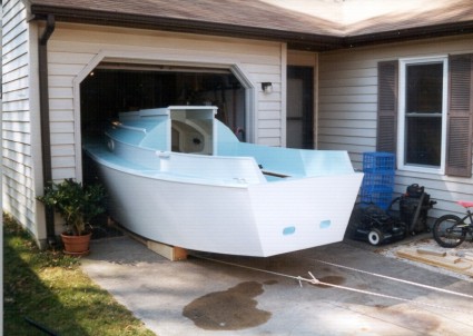
For the first time, I'm looking at the boat from farther than 2 ft. away. Wow.
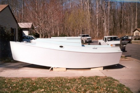
The boat is moved forward a bit on the frame to get ready for the "dry-retrieval" onto the trailer. The ballast is still not installed, so horsing the boat around is still possible.
Another look near the bow.
The same friend that helped me in the last turn-over brought his car jack and lifted the bow enough to get the first trailer bunks under the hull. Then I hooked the trailer's winch up to the bow eye (just visible near the knuckle), and winched the boat on the trailer. Initially I had to tip the trailer up a bit, but the whole process was really easy to do. I love it when a plan comes together.
Here we are with the boat turned around, on the trailer, with a quick look at the straps.
A future project will be installing guides near the aft part of the trailer to help position the boat during "wet-retrievals".
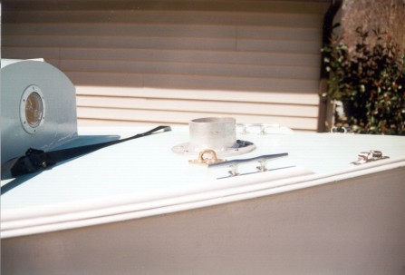
Now some quick pictures of the interior. This highlights the hatches and portholes which were installed quite easily. No more gaping holes to look at.
Another view, slightly to starboard.
All hatches and deck hardware were sealed with a silicon/polyurethane blend called Life-Seal.
A closeup of the porthole. I used acrylic glass for the window, and the frame is made of 1/4" ply. I would choose something different next time because it couldn't hold up to the bolts. Even with washers, some of the heads sunk in a bit.
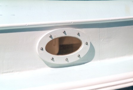
A close up of the bow and the hardware installed to date. There is a bronze padeye on the other side of the mast tube. Together they will be part of the boom vang. More visuals to come.
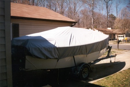
And finally, put to bed.
Now it'll be time to concentrate on the rig, rudder, and deck details.
Construction - VIII
Progress Report - Apr. to Jul. 2001
After enduring the usual problems and excitement associated with moving into a new house, it was time to return my attention to the boat. There is still lots to do. It's amazing how much time (and expense) can be absorbed with attaching hardware to the deck.
Then there's the rudder that I've been successfully ignoring up to this point. I glued together the parts some time ago, but I kept putting off the shaping the rudder to a NACA cross-section. Kirby provided a sheet of offsets for what the rudder should look like at 3 different "waterlines". So I cut out templates from plywood, grabbed my power planer, held my breath, and started creating lots of wood shavings. Once I got it close to something related to the template, then I continued with the belt sander.
The one thing I've learned about dating and marriage is that you aim for perfection, then marry the closest thing to it. The second time around, I did damn good. On the rudder, though, I stopped in the region of "good enough". I was a bit concerned about the rudder being too thin if I followed the templates exactly. So I left it a bit thicker and a bit fuller on the leading edge.
Here we see both the top and bottom parts of the rudder in the orientation that they'll be assembled. The foil part of the rudder has been coated with 10 oz. cloth for greater strength and to seal everything up tight. The plans show a diagonal member on the top part to resist the torsional stress on the case as the rudder is turned. My diagonal is slightly crooked so it won't interfere with the bottom pintle strap, shown here.
Most standard pintles are designed for rudders that are 1-1/2" thick. The case here is a little over 3" thick. So I bought the longest straps I could find and did a considerable amount of readjustment to get them to honor the new dimensions. The clip that holds the rudder in place is visible above the lower pintle.
Lining up the pintles with the gudgeons during installation is a bit of a practiced art. It only takes a fraction of a dight to make them bind or refuse to slip into place. It took a bit of encouragement (encouragement = hammer) before everything cooperated.
After I finally put the rudder together, I installed 2 control lines. One for raising the rudder, and one for holding it down. Both of these lines are led to cleats on top of the tiller. At this point I am skeptical that one small line will be enough to hold the rudder down, especially when moving along smartly.
The Deck
When I moved the boat to the new house, I hadn't installed the cockpit lockers yet. My biggest consternation was over the latches. I could buy those really nice elliptical snap clasps, but at $35.00 each I looked around for other cheaper alternatives. And the picture here shows what I installed. Perhaps not the best or the prettiest solution, but they work. On top of the hatch, the line is held by a knot and an eyestrap. There are no sharp points to cut skin or clothes. Each hatch is sealed underneath by a foam weatherstrip.
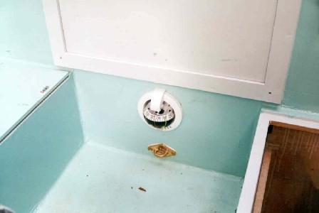
Here's a closer picture of the forward end of the cockpit. The compass has a LED light for night sailing. The bronze padeye below the compass is for attaching harnesses. Singlehanding and harnesses are just two things that always go together.
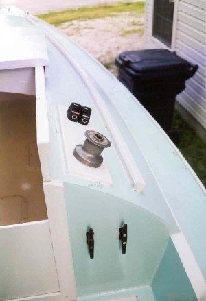
Here's a shot of the starboard side with the winch and rope clutches installed. The halyard and the outhaul will be led through the clutches. The cunningham will be led to a horn cleat on the port side. Missing here are the fairleads that feed the lines aft from the mast.
The plans don't specify a winch. I didn't think much of it until I read about one Seaward Fox owner who had trouble raising his similar sized mainsail. He gave up and installed a #6 winch on his mast. Winches are also good for hauling in stubborn anchors.
The two horn cleats on the bulkhead are for hanging any spare lines, like the extra 30 ft. of halyard when the sail is raised.
The Mast
One nice June day a semi-tractor trailer pulled up to my house and deposited a 45lb. box. I took the cardboard wrapping off and the result appears in this pic. My first duty beyond the careful inspection was to put the mast in the boat to make sure the base fit correctly. That was a scary moment. Not because I was nervous it wouldn't fit, but because man-handling a long pole a few inches shy of 31 ft. while balancing on a tiny foredeck was walking the fine edge of disaster. Fortunately it fit and I didn't break it, but it reinforced the need for a Mast Raising System.
Although Composite Engineering said that the mast would only suffer cosmetically from UV rays, I wanted to paint it to match the rest of my color scheme.
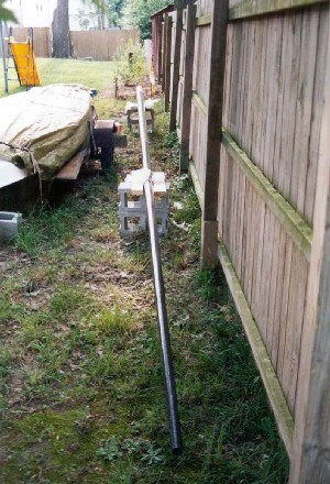
If you've ever looked at a galvanic chart, you'll see that carbon is at one end and aluminum is almost at the other end. When the two come together, like when the mast is in the mast tube and you add an agent like salt water, you get a combination that corrodes the aluminum. To prevent this, Comp. Eng. wrapped the buried part with standard fiberglass.
After the usual pattern of priming and painting, I attached the sailtrack, halyard block, and quite a few eyestraps.
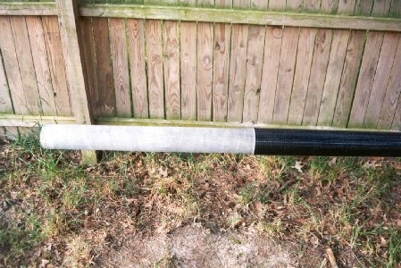
Here's a close up of the top, complete with halyard and windvane. I packed the top of the mast with epoxy and filler, then cut a slot for the sheave.
I've never worked with carbon fiber before. I learned quickly how tough it can be. I used stainless steel screws in pre-drilled holes to attach the sailtrack. Turning the screws became really tough duty. After snapping off several, I had to drill the holes slightly bigger before it would let me set them all the way in. I don't think they'll go anywhere.
The halyard does not go inside the mast as the designer recommends. Instead, I've fed the halyard through eyestaps on the front of the mast. This way, the mast remains watertight since there is no hole at the masthead, and the halyard will always follow the bend of the mast (critical to maintaining luff tension on unstayed spars).
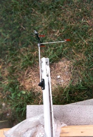
This pic shows the detail around the lazy jack attachment. The sailtrack is on the right, the halyard fed through an eyestrap on the left. The top part of the lazy jack is a 3/32" line that is tied to an eyestrap on each side of the mast. I chose to use line instead of the recommended wire because line is a little easier to rig and un-rig.
Screws were used for all of the mast hardware save for one: the gooseneck. Comp. Eng. recommended through-bolting the gooseneck fitting. That provided a bit of a challenge since the gooseneck is 5 ft. from the mast butt. I taped a wrench to a long stick, taped the nut and washer to the wrench, then slid the whole contraption inside the mast while feeding the bolt from the outside. It turned out easier than I figured.
The whole boom was assembled by Dwyer Mast from the dimensions I gave them. It arrived in my backyard a couple of weeks after the mast. The fittings at the ends of the boom allow the outhauls to be run internally.
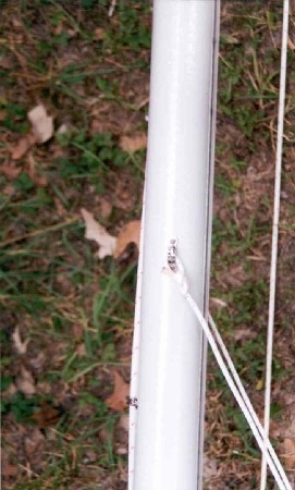
Here's a closeup of the gooseneck and tack fitting. Just like the rudder pintle straps, the gooseneck fitting had to be adjusted a bit to conform to the 5" diameter curve.
From the last two pictures it might be obvious that I was doing a dry run at putting the rig together.
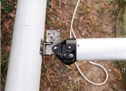
And here it is, complete with lazy jacks and halyard. The next logical step would be putting the rig on the boat, but first I needed to put on my engineering hat and concoct a...
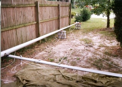
Mast Raising System
The mast, even with all the hardware, is still only about 45 lbs. Lifting it and swinging it around is not difficult. But it is very awkward to raise. Being able rig the boat on my own has always been important. So I built the aids shown in this pic. The mast crutch holds the butt in place and helps guide the rest of the mast while it is raised. Once vertical it is easy to slide the spar into the mast tube. The cross on the crutch allows the mast and the boom to sit side by side while I hook up all of the lines. You'll notice the boom is not attached to the mast yet.
The crutch on the stern was built to hold the mast and boom while traveling down the road. I built a smaller crutch that fits into the mast tube to hold the forward ends.
Once the spar is in place, I can connect the gooseneck, remove the Mast Raising System, and commence connecting the rest of the running rigging.
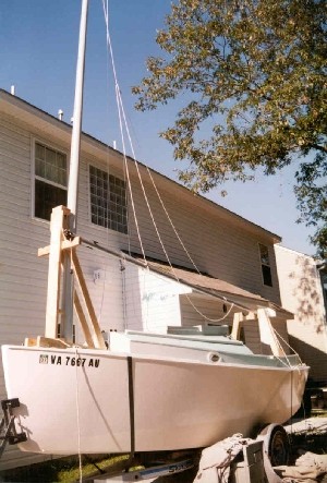
And here is a pic that attempts to show all of the rig at once. Pretty tough to do since the mast is so high. The tree behind the boat caused some difficulty since the mast would get hung up in the branches during the raising and lowering stages. Very annoying.
But! All this hard effort was for a good reason. Now I was able to confirm the locations of additional padeyes and blocks for organizing the numerous lines. And even more important, it gave me an opportunity to accurately measure the dimensions for the sail.
I didn't time the mast raising, but the mast lowering process, complete with all de-rigging and with no help, took 25 minutes. Not bad.
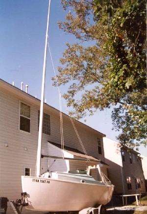
Here's a somewhat closer pic with most of the running rigging hooked up. Not yet installed are the cunningham and 2 reefing lines.
The boat's name shows up here, too. A sign shop made it from vinyl to my font specifications. Installed really easy.
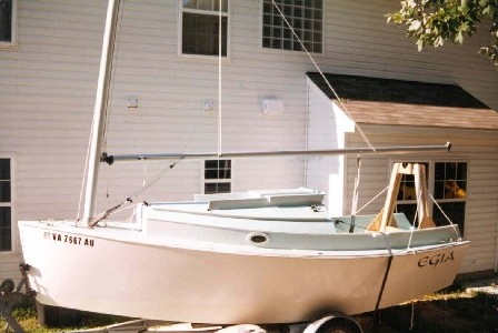
Here's a quick look at one of the oars, now painted. Instead of leathers and buttons, I used twine wrapped and knotted around the shaft for protection at the oarlock. I then painted it to help glue it all together.
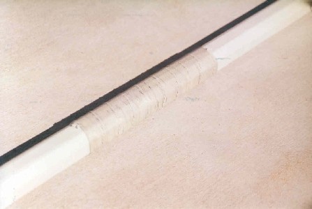
I am now waiting very patiently for delivery of my sail. The ballast has been installed. All safety, navigation, anchoring gear, and dock lines have been purchased. I still have fenders and a few organizational things to buy. But once the sail shows up, it shouldn't take long to get everything ready.
Launch
Progress Report - Aug. 2001
Upon receiving my sail, I rushed home and set the rig up horizontally in the backyard. After sliding on the sail I made a number of measurements for the reefing lines, outhaul, and cunningham. And as I expected, the boom was a bit too long. A lot better than being too short, though. So I cut about 4" off the aft end.
After another few trips to the store and a couple more evenings doing a odd jobs, the Great Event approacheth.
If you do any research on launching ceremonies, you get a multitude of different ideas. Many cases follow a set pattern. The builder launches the boat (with or without ceremony). Then after performing sea-trials, the builder legally turns the boat over to the owner. The new owner then performs a christening/launching/commissioning ceremony whereby the vessel gains a name, a spirit, and an official skipper.
I decided to follow the same procedure. As the builder, I would launch the boat and perform sea-trials the weekend before the Big Ceremony. That way I would have a chance to put the boat through its paces, become more comfortable with its performance characteristics, and still have a week to fix anything that broke. During the Big Ceremony, the builder (Me) will officially turn over the keys to the new owner (Me), designate the name, the spirit, and the new skipper (Me). Complete with bubbly over the bow (and into Me).
Okay, it's a plan.
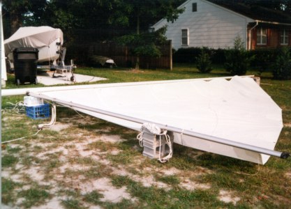
Sea Trials
In a break between rain showers, I towed the boat to the designated launching area and assembled the rig with the help of an eager friend and my bride. Backing the boat into the water, it came off easily into the water. Due to the inclement weather not many were using the boat launch, which was good since I needed a bit more room to get the sail up and everything squared away. The area around the ramp is pretty shallow, so I wasn't able to lower the centerboard or the rudder all the way until we were a good distance out. Even with appendanges retracted I was surprised at how little leeway we were making. Once the 5 kn breeze carried us into deeper water, it was time for the sea trials to begin in earnest.
The rudder was really easy to drop and hold in position. The centerboard was not so easy. If there was any side pressure against it, it would not move. Luffing up helped drop it down most of the way. We then eased into a close-reaching starboard tack. The first thing I noticed was the lack of pressure on the helm. After a short period I just let go. My friend and I looked at each other with wide eyes as the boat just tracked along by itself. Eventually a stronger puff arrived with a slight wind direction change and the boat just readjusted course itself and kept going. Our reaction was the same: "What an amazing boat!"
More tests were done. Slow speed manueverability, sailing all angles to the wind, tacking, gybing, intentional knockdowns. This last bit was done by luffing until almost stopped, pulling the main all the way in and turning 90 degrees to the wind. It heeled to 45 degrees and just stopped. Just a bit of the leeward rail was in the water at this point. More wind would be needed to get it to go any further. Knocking it over on starboard tack would cause the off-centerboard to ventilate at about 40 degrees of heel. Good to know. We took in both reefs to test out that gear. No problems. My thanks to Tim for the Seaward Fox site where he added a halyard winch. I used mine frequently and was very happy to have it. The rest of the running rigging worked perfectly.
I admit that going into the sea trials I was fully prepared for the boat to show some bad behavior. Even in 5 knots of breeze. I was continually amazed that nothing untoward came to pass. The rudder is very well balanced and has a lot of bite, even at slow speeds. Gybing was no fuss. Tacking was really easy (just turn the helm). Acceleration was great. And as I suspected, the boat is initially tender. From my experience in 6 Meters, though, I don't consider tenderness to be a bad trait.
After 2 hours another rain storm approached so we headed back to the ramp. Getting the boat back on the trailer was not a problem, despite not being able to back the trailer all the way down. That tested the bow eye successfully. Two final observations: the boat floated on her lines and never leaked a drop of water.
Things I didn't get to do is test in waves and higher wind conditions. Somehow I think that will come in time. Oh, yeah, and I didn't test the rowing capability. Call it downright laziness.
Several days of downpours revealed another flaw. My cockpit hatches leak like sieves. I will have to redesign that system (Heavy Sigh).
Launch Day
Perfect conditions greated us on August 25. Sunny, winds N-NE at 15 - 18 kn, and warm. A friend took most of the pictures here with his fancy digital camera. Click on the thumbs to see the full picture. Back to the designated launch area at Willoughby Bay we went. My bride set up a great food spread, I set up the boat, guests arrived. Among the entourage was Alleluia, a Norwalk Islands Sharpie 26. It became the press boat.
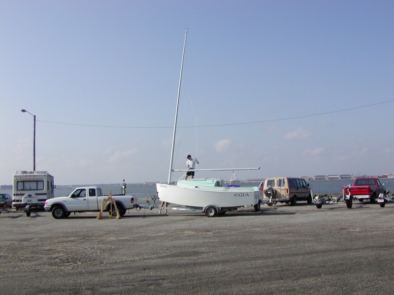
With the boat properly dressed, I said a few words of thanks, my bride did the sponsor thing of making a small speech and spraying the boat with champagne. We then proceeded with the launching evolution.
The burgee is from the (University of) Washington Yacht Club where I first learned to sail.
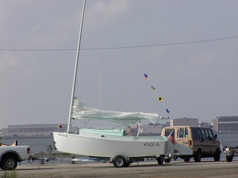
Here I'm coaxing the boat off the trailer. Sliding it off and on is remarkably easy.
This picture also shows the intricate spaghetti of control lines around the mast. In total there are main halyard (left side), boom vang with strap, outhaul, cunningham, reef outhaul #1, reef outhaul #2. It all works out without too much binding.
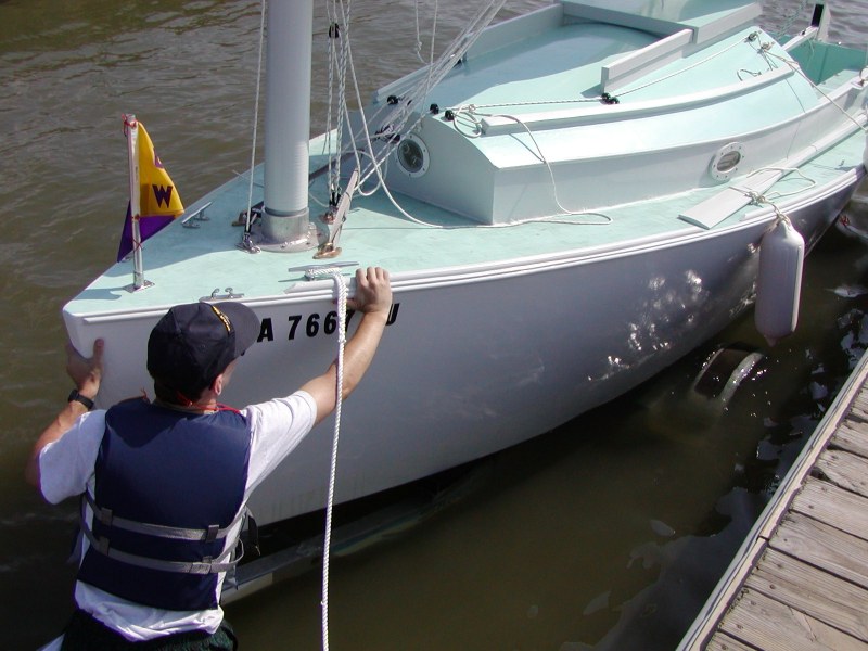
She's floating! These fancy digital pictures most accurately reflect the green color of the deck (your monitor may differ).
A number of people have warned me about the hazards of lazy jacks. I've found mine to be pretty benign. The only time they get caught is during the initial raising and it's no fuss to clear them. Reefing, or taking out reefs, doesn't foul at all.
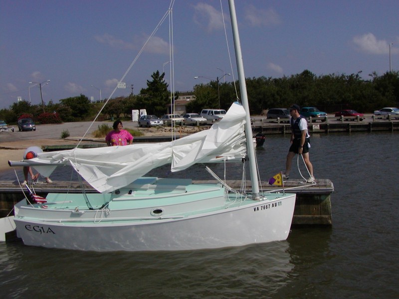
So I raised the sail, loaded up the first batch of guests, and off we went. Once beyond the shadow of the highway bridge the wind made it's full force felt. I decided pretty quickly that we needed to take in a reef. This picture caught me in the midst of the process.
Even overpowered the boat didn't exhibit any bad behavior. The helm was always pretty tame regardless of gusts, people walking around, or the course. But there is one thing I found in the stronger breeze. Like a Laser and Finn, if you go dead downwind it will rock gunwale to gunwale if you're not careful. Heading up a bit stops the rolling.
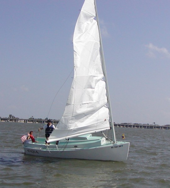
Here we are properly trimmed with a single reef and a bone in her teeth. The sailmaker tried to convince me that the reefs I requested were too deep. Since we had plenty of power here in the gusts, I am very glad I stuck to my guns.
As in the sea trial, the short fetch didn't allow much in the way of waves. So the jury is still out on how she does in chop or bigger waves.
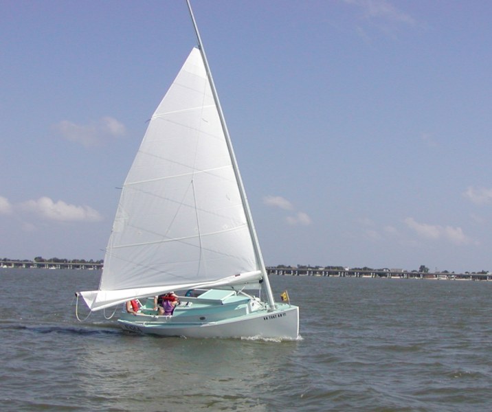
Here she is at speed. Please forgive the dragging fenders. Since I was back and forth to the dock to give rides I didn't bother stowing them. I like the photo though.
Again, the oars stayed stowed on the side decks. I take that as a good thing. I'm still a bit curious about how they'll work, but I'm sure that will come in time.
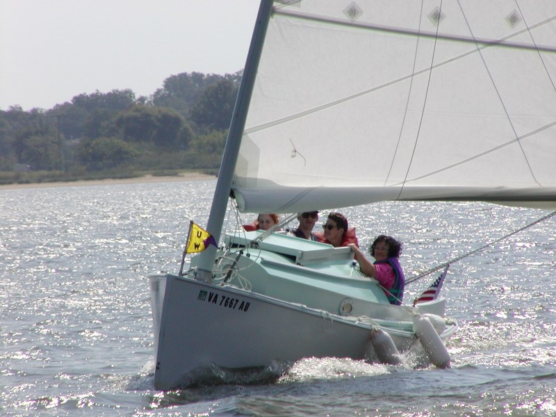
This picture is probably one of the few times we'll be ahead of Alleluia. Although the starboard cockpit drain appears underwater, it is actually right at the water's edge. Despite 4 people in the cockpit, I never got more than a cup of water through the drains. I was surprised since I expected a bit more.
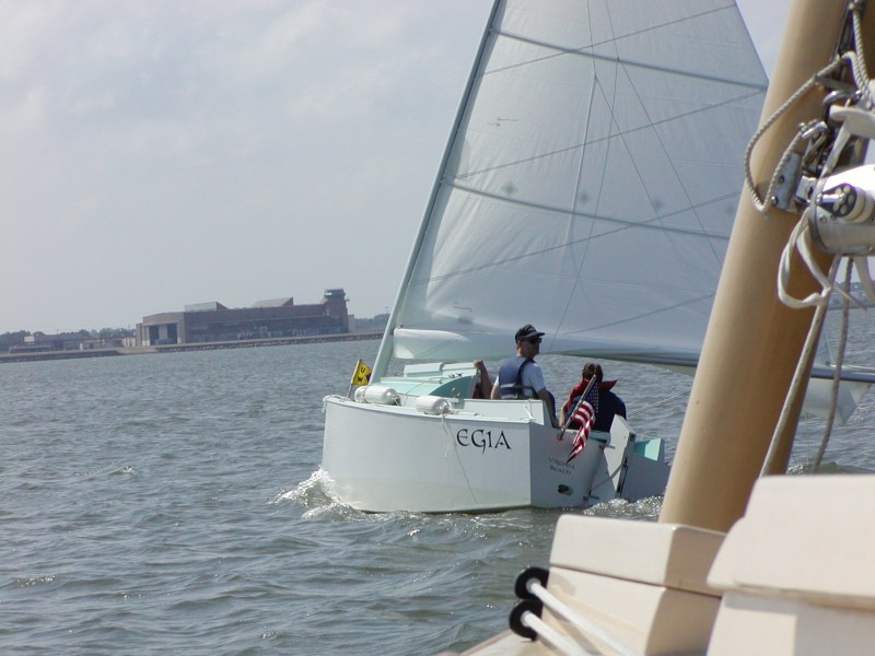
Here's a picture of the aforementioned Alleluia. You can see the family resemblence. This boat was built by a Connecticut boatyard under the watchful eye of the designer. To my knowledge it was the second 26 made. The current owner purchased her several years ago. She remains in the original configuration (and name) since her launch in 1986.
Eventually our party came to a close. A great ending to one chapter and a start on the next. From the first cut to launching took exactly 2 years and 9 months. Total construction labor was 619 hours.
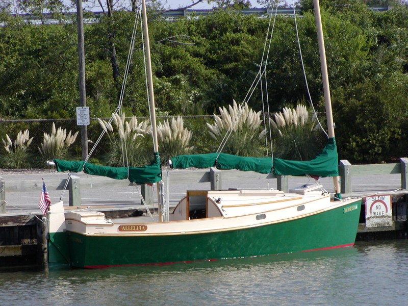
Egia
Pronounced Egg'-ee-ah, this name comes from Norse Mythology. The god and goddess of the sea are Ægir and Ran. Together they had nine giantess daughters, often referred as Wave Maidens. Egia is one of these maidens. Legend has it that when they favored a sailor, they played in the waves around his ship, pushing him forward to his destination. Well, I guess I can always hope.
Now you might think that I'm all misty-eyed over the end of Egia's construction. That I'll miss those evenings in the shop making sawdust or mixing epoxy. Not so. You see, I've already cut the bulkheads for my next boat project. And for those in the back snickering, the next boat will not be bigger. Rather, it is much smaller--a Mixer. But I don't expect to be working on it much before winter sets in. Instead I'll be S-A-I-L-I-N-G!
Materials
Costs
Even the most financially incompetent would like to know how much a project like this will cost, so here is a breakdown of what has been spent on materials. Since I purchase on a "as-needed" basis, this list will be updated frequently. I am only including items that will become a permanent part of the boat. Timber for the strongback, paint brushes, gloves, sandpaper and so forth are not included. The Commissioning section shows things that were needed to get the boat to the water and to use it safely. Amounts are in US Dollars.
| Wood | Poplar for Various | $113.35 |
| Aspen for Traveler Beam | $9.37 | |
| Marine Fir Ply 1/4" - 4 | $141.03 | |
| Marine Fir Ply 3/8" - 17 | $807.52 | |
| Marine Fir Ply 1/2" - 5.5 | $303.09 | |
| Milled African Mahogany & Fir | $112.86 | |
| Milled Honduras Mahogany & Fir | $424.89 | |
| Milled African Mahogany for Trim | $163.65 | |
| Ash for Oars | $48.07 | |
| Fasteners, Epoxy, and | 1" #6 Zinc Wood Screws | $36.76 |
| Fiberglass | 1-1/4" #6 Zinc Wood Screws | $9.11 |
| 1-1/2" #6 Zinc Wood Screws | $3.02 | |
| 3/4" Bronze Boat Nails | $3.65 | |
| System Three #1 Hardener - 1 gal. | $53.00 | |
| System Three #2 Hardener - 2.5 gal. | $110.00 | |
| System Three #3 Hardener - 2.5 gal. | $118.00 | |
| System Three Resin - 12.5 gal. | $490.40 | |
| West System 105 Resin - 1 gal. | $64.53 | |
| West System 206 Hardener - 0.8 quart | $25.60 | |
| Filler - Collodial Silica | $122.66 | |
| Filler - Microlite Filler | $10.24 | |
| Filler - Microfibers | $16.20 | |
| Filler - Graphite Powder | $6.79 | |
| White Paste Pigment | $7.28 | |
| 10oz Woven Cloth - 35 yds | $262.08 | |
| 20oz Triaxial Cloth - 6yds | $74.88 | |
| Caulk - 3M 4200 | $28.18 | |
| Caulk - Polyurethane (Generic) | $11.73 | |
| Caulk - Silicon | $9.20 | |
| Hardware | Harken Centerboard Control Blocks | $89.93 |
| Various Nuts, Bolts, Washers, Screws | $199.50 | |
| Harken Eyestraps - 96 | $109.89 | |
| RWO Rudder Control Blocks | $28.14 | |
| Harken Mainsail Traveler System | $268.04 | |
| Harken Mainsheet Blocks | $99.41 | |
| Harken Boomvang Blocks | $71.29 | |
| Various Blocks | $31.33 | |
| Various Shackles | $14.90 | |
| Various Padeyes | $83.95 | |
| Hatch Hinges and Locks | $143.64 | |
| 8" ABI Yacht Cleats - 4 | $41.96 | |
| Chocks - 1 Pair | $16.31 | |
| Centerboard Pennant | $10.98 | |
| Oarlocks - 2 | $31.12 | |
| Various Nylon Cleats | $56.37 | |
| Fairleads - 8 | $7.90 | |
| Spinlock PX Clutch - 2 | $62.69 | |
| Lewmar 6A Winch | $104.49 | |
| Winch handle | $26.06 | |
| Suunto B-116W Compass | $125.39 | |
| Running Light | $20.89 | |
| U-Bolts - 6 | $28.29 | |
| Rudder Pintles and Gudgeons | $117.75 | |
| Outhaul S-Hook | $4.17 | |
| Rig | Carbon Fiber Mast | $1822.89 |
| Various Dacron Line | $229.43 | |
| 5/8" Sail Track - 30 ft. | $114.91 | |
| Masthead Sheave | $7.30 | |
| Shackle | $6.26 | |
| Assembled Boom + Gooseneck | $703.94 | |
| Davis Windex | $30.29 | |
| S/S Ring | $5.21 | |
| Ronstan Small Blocks - 2 | $12.53 | |
| Nylon Webbing | $5.12 | |
| Sail | $1392.99 | |
| Finishing | Interlux Epoxy Barrier-Kote - 6 Qt | $124.29 |
| Interlux Reducing Solvent - 2 Qt | $27.14 | |
| Interlux Premium Yacht Enamel - 2 Qt | $31.33 | |
| Interlux Brightside White - 3 Qt | $62.67 | |
| Interlux Brightside Seattle Gray - 2 Qt | $41.78 | |
| Interlux Brightside Sea Green - 1 Qt | $20.89 | |
| Interlux Poly Non-Skid - 1 Qt | $21.93 | |
| Boat Graphics | $36.23 | |
| Miscellaneous | Lead Pigs (700 lbs.) for Ballast - 25 | $625.88 |
| 8x12 Bomar Inspection Hatches - 5 | $203.96 | |
| 6" Bomar Round Deckplate | $10.96 | |
| 4" Beckson Round Deckplate | $10.44 | |
| Mast Tube Assembly | $710.60 | |
| Centerboard Assembly | $668.80 | |
| Aluminum Conduit for Various | $7.24 | |
| Portlight Glass - 2 | $22.74 | |
| Oarlock Twine | $2.06 | |
| Weather stripping | $8.73 | |
| Flag holders | $17.33 | |
| HIN Tags | $10.45 | |
| Construction Total | $12,377.85 | |
| Commissioning | Trailer plus modifications | $681.56 |
| Sea Anchor (Army Surplus) | $22.50 | |
| Horn | $10.44 | |
| 5 lb. Folding Anchor Kit | $32.10 | |
| 13 lb. Anchor Kit | $68.96 | |
| Leadline Kit | $17.72 | |
| Origo Flare/Locator Kit | $52.24 | |
| Logbook | $17.75 | |
| 7 X 50mm Binoculars | $62.99 | |
| First Aid Kit | $31.34 | |
| Kidde Fire Extinguisher | $13.57 | |
| Docklines | $25.02 | |
| Fenders - 4 | $20.90 | |
| ICOM Handheld VHF Radio | $139.99 | |
| Cotter pin kit | $4.17 | |
| Sail Repair Tape | $8.35 | |
| Safety Whistle - 2 | $3.55 | |
| Overall Total | $13,591.00 | |
Tools
Let's face it. All the boat building dreamers out there would love to have the tool arsenal of the New Yankee Workshop along with the levitated reality of showing the construction as a 30-minute exercise. Building a boat is a very time consuming process worthy of Thomas Edison's remarks: 5% innovation and 95% sheer drudgery. Since I don't have vast monetary resources, I make the drudgery part entertaining by thinking of ways I can do the job without having to make endless runs to Home Depot for yet another $60 gizmo. Think of it this way: the less you spend on tools, the more money you have to pump into the boat. To show other potential builders (and anybody else) that it can be done with not a whole lot, here is a list of tools that I am using for construction.
| Hand Power Tools | Jigsaw (duh!) | Belt Sander - 3"x24" (R.I.P.) |
| Power Planer (best $60 I ever spent) | High Speed Drill - small | |
| Big Drill | SkilSaw (rarely used) | |
| Orbital Sander | Belt Sander - 3"x18" | |
| Hand Tools | Small Planer | Various sized screwdrivers |
| 6" C-clamps - 3 | 2-1/2" C-clamp - 1 | |
| 4" C-clamps - 1 | 2" C-clamps - 3 | |
| 3" C-clamps - 1 | Hammer | |
Notice that there are some things that are missing. Like a table saw. I had a beautiful table saw (an inheritance) for my other boat building forays, but I had to sell it after Failure #2. This time I decided to try to get along without it and so far I've been pretty successful. If anyone has read Annie Hill ( Voyaging on a Small Income ) and think that I'm starting to sound like her, I don't take financial frugality to such a masochistic extent. Since this boat will be responsible for my life while I'm on the water, I will cut no corners in quality of materials or workmanship. But I will agree with the Hills that building a smaller boat allows for extra money to lavish upon it, like a carbon fiber mast or a top-of-the-line sail.
Other Supplies
No doubt you've figured by now that I'm leaving out some indispensible items, and so I will cover them here. This is a section that is mostly my opinion and doesn't involve any right or wrong way to do things.
Brushes - I used to buy the really cheap hair brushes for epoxying, and then throw them away after one use. I found that the thickness of the epoxy frequently pulled out some of the hairs, leaving me to pick them out later. Drawing from some advise in H. "Dynamite" Payson's books I started buying the really cheap brushes with the plastic bristles, and then after each use I clean them in acetone. Surprise, surprise, they last for quite a few uses and they keep all of their bristles.
Vinyl Gloves - In my opinion an essential part of dealing with epoxy. A number of people become sensitized to the epoxy after repeated exposure (well known builder, author, and adventurer John Guzzwell being one of them). I haven't yet, but I might. Gloves are the minimum for protection. I would add long pants, especially for the men. I have had to pick solidified epoxy out of the hair on my legs and Hey!, it hurts, okay?
Epoxy Mixing Containers - Get the small plastic cups found in the paint section of most hardware stores. If you have hardened epoxy left from a job, you can wiggle the plastic enough so the epoxy pulls loose. Then you can reuse the cup. Don't forget lots of tongue depressors, too. I clean mine with a rag after each use so I can reuse them over and over. And think about it, once a tongue depressor is saturated with hardened epoxy it becomes the strongest piece of wood in medical history.
Face Mask - I just use the cheap ones, but I think they are essential when dealing with epoxy fillers. Collodial silica is similar to asbestos and flies all over the place. Apparently graphite powder is equivalently nasty stuff. Although I don't use them, face goggles would probably be a good idea also. I'll probably break down and get a pair when I start the large-scale sanding/fairing of the hull.
Vacuum - Yep! I finally succumbed to buying a Shop-Vac. But they were on sale so I couldn't resist. The major advantage of having a vacuum was apparent after I turned the hull over. When it was on the building frame, any creation of sawdust fell out of the boat. But having the hull right side up means that gravity is no longer on your side. 3 hp seems to do the trick. My son was pretty impressed with its power.
Wood
Let me make a few comments about wood. There is a lot of excellent wood out there that is tailored for boat building. You constantly hear about oak, mahogany, teak, sitka spruce as ideal woods for different applications. Other woods, on the other hand, are generally shunned from marine use. The crimes are rotting, no strength, and won't bend without breaking.
Now, the biggest problem with the "good woods" is that you never find them readily available. Like as not they are grown in some far off rain forest, kiln dried in special ovens, then packed on a leaky ship that limps around the world twice before delivering it the nearest port. The price you pay to get it to your door makes you wonder if you are singlehandedly financing a third world nation's economy. When you trudge down to your local lumber supplier, which might just be a nationwide chain, what you can get will depend on the selection and the price that you can afford.
My choices came down to pretty much the same issues of affordability and availability. But there are 2 woods on my material list that don't fit the traditional boat building paradigm. I used poplar for the stem, skeg, parts of the rudder assembly and the hatchboard rails. Poplar is a soft hardwood, if that makes sense. It is light, fairly strong, and cheap. Poplar is also unstable (meaning expands and contracts with changes in water content), can change significantly in quality from board to board, and is fairly porous on the end grain. Hence the aversion to its use on boats. Using epoxy changes the rules somewhat. My personal experience is that epoxy prefers wood that is somewhat porous to achieve a superior bond. When I broke up Failure #1, the weakest glue joints were those involving oak. Poplar's unstable attribute is solved by simply sealing the whole board with epoxy and paint, something that I'd do as a matter of course anyway. My other requirement is how well the wood holds a screw. Poplar is not great, but it's acceptable. I didn't have any trouble with the bigger screws in the stem to hold the chine logs in place. The other non-traditional wood I've used is aspen. This is another hardwood that is soft, light, and cheap. It is also weak, likes to warp after drying, doesn't hold a screw very well, and is pretty porous. But what attracted me to using it as the traveler beam was aspen's resistance to breaking. When it fails, it doesn't break at one single point but rather pulls up the fibers over a wide area. Sounds perfect for a traveler that needs strength over the entire beam. Again, the whole piece will be sealed with epoxy and painted over.
Epoxy is not a cure-all, but it does allow consideration of other woods that weren't practical before.
"Ignoranti quem portum petat, nullus suus ventus est."
"If one does not know to which port one is sailing, no wind is favourable." Seneca the Younger, c. 3BC-65AD
Postpartum
No, this isn't a treatise on depression. It's a review of the construction process and a critical look at what I kind of boat I got in the end. This is intended to be really useful to anyone who is thinking seriously of building a Norwalk Islands Sharpie or a boat of similar design.
Construction
It would be better to call this section Coulda, Woulda, Shoulda . Some of the things I would have done differently have already been mentioned in the previous pages, like how to apply fiberglass. But there are still a few things that appear when I put on my 20-20 hindsight glasses.
Design
Overall I am really happy with the minor changes I made to the original plans. The space under the port "head" is really useful. The longitudinal bulkhead under the bunks is also really a bonus since it strengthens the bunks themselves and prevents anything stored underneath from sliding around too much. There are 3 things that I would have done differently about the construction if I were to start over. First, I would have designed the centerboard to be thicker. Several builders did this in Australia, but when I found out I had already made the trunk. The purpose of a thicker centerboard is better efficiency since it could be shaped as a NACA foil. This would definitely improve windward performance. Second, I would have had the mast tube built after the mast was made. Whether carbon fiber, fiberglass, or aluminum is used, availability of mandrils is the critical component of what you can get for a reasonable price. The mast tube can then be made to fit later. Lastly, I would have designed the cockpit hatches differently. I'm not sure at this point what they should have been. Making them like the ones seen on production boats would have taken a month of Sundays to build. As it is, I'll have to experiment this winter on making the ones I have more waterproof.
There's more about the boat's balance under sail under the Sailing section, but there's something about the design that should be mentioned here. Because the boat is so well balanced under full sail with the bigger rig, I would seriously consider some very subtle design changes if I picked the smaller rig. Namely, either moving the mast aft a few inches or moving the centerboard forward a few inches to compensate for the difference in Center Of Effort. Another choice would be to make the centerboard so that it could be lowered farther to a more vertical orientation, thereby moving the Center of Lateral Resistance forward just a bit. The benefit of this change would be better handling when reefed, especially double reefed when the COE is so far forward.
Building
Having a bigger shop would have really been nice. Sure, I get that feeling of pride that I was able to do it all in a 10 ft. by 20 ft. space, but what it cost me was time. Time to move things around so I could work; time to move it all back when I was done for the day. Time when I couldn't work because it was too hot or too cold. Having a radial arm saw to do the more precision cutting would have been nice, too, but I didn't have the room for it.
I didn't follow the designer's exact order of construction, but then I don't think any builder would. This is especially true when several things things can be worked on simultaneously to save time. This becomes harder to do once the boat nears the end of construction so it seems like things progress at a slower speed.
I was pretty happy with the materials I selected. Some of the fir plywood would leave a ragged edge around my saber cuts, but most edges were buried behind epoxy goop so you can't tell. Phillippine mahogany ply cuts a better edge, but for my area it is too expensive.
Speaking of expensive, it would have been better if I spread out the more expensive components over the whole construction period. Sailing hardware, mast, boom, sail, and trailer were all bought at the end, making the cash outlay pretty painful. Keeping a close eye on discounted sales and researching sources for those things you don't want to build should start as soon as the first board is cut.
Many internet forums, like Wooden Boat and rec.boats.building newsgroup, provide no end of different solutions to many different puzzles. I've chimed in on occasion with my own opinion and experiences. But like many other topics, building a boat is part science, part art, and mostly grunt work. How things are done are really up to what the builder feels comfortable doing based on his/her strengths and weaknesses. I was often confused by the wealth of information and advice available. In the end I just processed what I needed and left the rest.
As a non-professional builder, what is the value of your time? Well, $0.00, to be precise. I found this to be the case when Egia was surveyed for insurance. I figured I had spent $12,000 in materials and 600 hours of labor. 600 hours of professional labor at $10 an hour would be $6000. So the boats total value (low end) would be $18,000, minus a couple thousand because the finish is not quite professional. Surveyor's value? $12,000. And that's only because I had receipts to show it. It probably would have been lower. The surveyor's comment was, "Homebuilt boat? Nobody wants to buy a homebuilt boat." Despite the blow to my ego, I know he's right. I would be very hesitant about buying a homebuilt boat because I don't know how it went together. But fortunately I didn't build Egia to sell it. Besides, the side benefit of a lower value is that the insurance rates are lower.
Sailing
As a reminder, I built Egia with the original tall mast and a 205 sq. ft. mainsail. Kirby now recommends the mast to be 5 ft. shorter and the mainsail size around 180 sq. ft. The ballast is 700 lbs. of internal lead ingots. I haven't moved them around from my original plan, but like Klaus S. found with his boat, the stern squats a little too much. Putting a couple of people in the cockpit causes the transom sink a couple of inches when it should just touch the water. I think the amount of ballast is just right, but I need to move some of it forward to make the trim more balanced.
Up to this point I have had Egia out in Beaufort scale winds of Force 0 to 7. In really light air (Force 0 to 1), the boat is very spritely. The narrow waterline, low wetted surface, and big sail allow the boat to scoot even if the water looks like a mirror. And she'll climb to weather like a witch on a broom with a tacking angle of around 75 to 80 degrees. As the breeze increases to Force 4, it's time for the first reef. Tacking angle at this point increases to around 90 to 95 degrees. You can still pull the main to the centerline, but the combination of wind force on the freeboard and the inefficient plate centerboard contrive to slow the boat to a crawl. It's better to let the boom out some and she'll pick up speed. Once the wind increases to Force 6, it's time for the second reef, which on my sail leaves about 75 sq. ft. At this point going to windward is a bit more strenuous. Tacking angle is 95 to 110 degrees, but that depends a great deal on the sea state. With 2 reefs, the sail area moves forward, creating lee helm upwind. I found that I was carrying 10 - 20 degrees of lee helm on a close hauled course in Force 6 - 7 conditions. This can be reduced somewhat by letting the sail twist more, although I found the lazy jacks began to interfere with this intention. Once I bore off to a beam reach or broad reach, the lee helm went away. Generally Egia will gain ground to windward into Force 7 (with no opposing current) but that's the limit. Given the right conditions downwind (steep seas and loads of breeze), Egia will surf down the waves and punch into the back of the wave ahead. I've done it a few times, though, without ill effect. In these same conditions, quite a bit of pressure is required on the rudder to prevent the boat from rounding into the wind. This is due to the sail area being out to one side, the pull on the mainsheet trying to yank the stern around. The advantage of this scenario, as I found out, is little chance of an accidental gybe. One last comment about my Force 7 experience: I never gybed, I always tacked around. Force 8 is too much even downwind for a double reef; at that point it would be better furling the sail and riding it out under a bare pole if you have the sea room.
In general, performance is probably affected by the how the sail is designed and how it interacts with whatever mast is made. A bendier mast and a flatter sail would likely behave a bit differently than mine.
The freeboard of the NIS designs do make them pretty dry during sailing. I've gone through tidal washing machines with nothing more than an occasional splash over the rail. The cockpit coaming really helps keep things dry, too. And despite the flat bottom she never pounds.
If you are looking for a boat that is as stiff as a church, then the NIS is not for you. 25 degrees of heal is easy to reach. But it does stiffen up the more it heals. Once I screwed up a tack in the Force 6 stuff (with 1 reef, not 2) and got pressed over to the point where the cabin porthole was just at the water's edge. I was a bit preoccupied at the time to look at the clinometer, but it was probably around 50 degrees. That was the worst case so far, and the boat popped back up and kept going without a whimper. I still plan to do some stability testing to get a better picture of the boat's hydrodynamic attributes.
I am very pleased that I loaded up the deck with so much sailing hardware, like traveler, cunningham, 4:1 outhaul, boom vang, etc. It turns out that the sail is so large that the boat responds to the slightest trim change. Having all those strings to pull really helps keep the boat running efficiently. Even if cruising. Egia will average over 5.5 knots downwind in Force 7, which is pretty good considering a displacement boat on a 16 ft. waterline.
One small note about the centerboard not actually being on the centerline. I do notice a slight difference in speed between port tack and starboard tack when going upwind.
Cruising
At this writing I have done a number of cruises. Most of them were singlehanded, the remainder with my bride. For one person Egia is quite comfortable. Everything is close at hand without being clausterphobic. Egia's ability to steer herself even for short periods allows time to navigate, make a sandwich, check the depth with the leadline, even clean a dirty anchor in the cockpit. For two people it's still quite comfortable, but a careful dance is required when both are moving around below. The sleeping bunk is very commodious for two adults. Three adults is about the maximum I'd want to have aboard, especially since the sleeping arrangements would be difficult.
There is certainly plenty of storage; I've yet to use it all even though I've always packed too much food. When singlehanding I make do without a cooler since I don't have a convenient place to put it. Cooking is done with a gimbled propane bottle stove. The stove is so easy to operate I can't imagine it any other way, plus I don't have to worry about spilling my dinner when the boat rolls from a passing wake.
As of March 2002 I finished making the cushions. It was quite easy, with a little inspiration from Dave and Mindy B . I bought 5" foam from a wholesaler, the coated packcloth from Outdoor Wilderness Fabrics, and with a quick lesson from my bride on how to use the sewing machine I proceeded. The result was not professional, but better than I had expected.
Modification 1
No doubt about it, a boat building project never finishes; it just goes through different phases. So here I will list the work I've done to the boat since launching it.
Cockpit Hatches
My solution for securing the hatches, shown again here, was inexpensive, ingenious, and totally useless. I couldn't get them tight enough, even with weather stripping, to prevent them from leaking. Actually, "leaking" is probably not a strong enough word.
During a cruise in May 2002, it rained overnight while I was at anchor. I stayed warm and perfectly dry in the cabin, but in the morning I was sponging 3 inches of water out of each locker. If this wasn't bad enough, all the exposed bolt ends where the hardware was attached were poking holes in cushions, pants, and flesh.
The latter problem I fixed with shorter bolts and cap nuts. And after finding a good deal on some brass cam-style latches, I dispensed with the line-and-cleat disaster. The appearance of the cockpit has gone from chintzy to nautical.
Here's a picture after the conversion. With application of rubber gasket around the edges, I'm happy to report that the hatches are now mostly rain proof. Notice I didn't say waterproof.
One additional thing I've done is beef up some weak areas of the rudder. I've been keeping a close eye on it, since several places suffer more strain than others. So far, two hairline cracks have appeared in the rudder box, one near the tiller, and another at the bottom forward section where it was separating from a glue joint. Adding a layer of fiberglass at the stressed area seemed to stop the problem.
Several Projects
During the winter of 2003/2004 I tackled a number of outstanding projects. I was never happy with the finish of the hull, so it was time to strip off the paint and fair out all the rough spots. It took many hours of sanding, spreading on compound, and more sanding, which is exactly why I didn't do it originally.
The plywood portholes and the aft bulkhead of the cabin started to check (display cracks in the veneer, so it was time to solve that. In the process of taking the ports off, the ply broke, so I made new ports from MDO. That stuff shouldn't check, and it holds up better to bolt heads than ply (see earlier comments). As for the bulkhead, there was no choice but to sand down to bare wood and fiberglass everything.
I even fiberglassed the dropboard trim. I was unhappy with was the original grey color I picked for painting the trim and other highlights. It was not dark enough to show much of a contrast with the white hull. So I went with a darker grey color and repainted all the relevant surfaces.
My bride had complained about the lack of shelf space in the boat, so I proceeded to install 5 of them peppered about the cabin. All of them have the obligatory fiddles so things won't be tempted to fly around. It does make the cabin a bit more liveable.
Another nitpicky item was the ballast. Egia has always listed a few degrees to starboard, mostly likely due to the weight of the off-center board. I took this opportunity to move some of the ballast to port and forward (which required some new tie-downs, etc). Now it seems more correctly level. It will certainly make it easier to row.
In 2012 I sold the boat to a family in New York. Long live Norwalk Islands Sharpies!